Thursday, February 26, 2009

Gigabit Ethernet

Gigabit Ethernet (also referred to as GigE) is a site-to-site and Internet access service that when used by enterprises is intended to increase network access speeds so that they more closely match speeds in LANs. GigE operates mainly over fiber-optic cabling. A key advantage is that it uses the same protocol used in LANs, making it less complex to connect to customers' networks and simpler to upgrade to higher speeds.


GigE is used in enterprises' internal networks, carriers' metropolitan area networks (MANs), and by enterprises to access the Internet or connect to other sites. As an Internet access service for enterprises, GigE is generally offered at speeds ranging from 10 Mbps to 1000 Mbps. Enterprises also use it for point-to-point communications between LANs in metro areas and for access to national VPNs for site-to-site communications. Customers use either a router with an Ethernet port or an Ethernet switch to connect to carriers' Ethernet offerings. Cisco, Extreme Networks, Foundry Networks and Nortel manufacture GigE service switches. GigE does not require a CSU/DSU (Channel Service Unit/Data Service Unit) (used for T-1 type services), a T-1 multiplexer, or a FRAD.

Tuesday, February 24, 2009

Ethernet Frame Type Wrap-Up

The 802.2 variants of Ethernet are not in widespread use on common networks currently, with the exception of large corporate Netware installations that have not yet migrated to Netware over IP. In the past, many corporate networks supported 802.2 Ethernet to support transparent translating bridges between Ethernet and IEEE 802.5 Token Ring or FDDI networks. The most common framing type used today is Ethernet Version 2, as it is used by most IP -based networks, with its EtherType set to 0x0800 for IPv4 and 0x86DD for IPv6.
There exists an Internet standard for encapsulating IP version 4 traffic in IEEE 802.2 frames with LLC/SNAP headers. It is almost never implemented on Ethernet (although it is used on FDDI and on token ring, IEEE 802.11, and other IEEE 802 networks). IP traffic cannot be encapsulated in IEEE 802.2 LLC frames without SNAP because, although there is an LLC protocol type for IP, there is no LLC protocol type for ARP. IP Version 6 can also be transmitted over Ethernet using IEEE 802.2 with LLC/SNAP, but, again, that's almost never used (although LLC/SNAP encapsulation of IPv6 is used on IEEE 802 networks).

The IEEE 802.1Q tag, if present, is placed between the Source Address and the EtherType or Length fields. The first two bytes of the tag are the Tag Protocol Identifier (TPID) value of 0x8100. This is located in the same place as the EtherType/Length field in untagged frames, so an EtherType value of 0x8100 means the frame is tagged, and the true EtherType/Length is located after the Q-tag. The TPID is followed by two bytes containing the Tag Control Information (TCI) (the IEEE 802.1p priority (QoS) and VLAN id). The Q-tag is followed by the rest of the frame, using one of the types previously described in the prior "Word of the Day" (see below).

Summary of the Major Ethernet Frame Types
• The Ethernet Version 2 or Ethernet II frame, the so-called DIX frame (named after DEC, Intel, and Xerox); this is the most common today, as it is often used directly by the Internet Protocol

IEEE 802.2 LLC/SNAP frame

• Novell's non-standard variation of IEEE 802.3 ("raw 802.3 frame") without an IEEE 802.2 LLC header.

• IEEE 802.2 LLC frame

Monday, February 23, 2009

There are several types of Ethernet frames:
• The Ethernet Version 2 or Ethernet II frame, the so-called DIX frame (named after DEC, Intel, and Xerox); this is the most common today, as it is often used directly by the Internet Protocol
IEEE 802.2 LLC/SNAP frame
• Novell's non-standard variation of IEEE 802.3 ("raw 802.3 frame") without an IEEE 802.2 LLC header.
• IEEE 802.2 LLC frame

Today we will describe the Novell's non-standard variation of IEEE 802.3 ("raw 802.3 frame") without an IEEE 802.2 LLC header (which also touches on LLC frame)

Novell's "raw" 802.3 frame (no LLC header)
Novell’s "raw" 802.3 frame format was based on early IEEE 802.3 work. Novell used this as a starting point to create the first implementation of its own IPX Network Protocol over Ethernet. They did not use any LLC header but started the IPX packet directly after the length field. This does not conform to the IEEE 802.3 standard, but since IPX has always FF at the first two bytes (while in IEEE 802.2 LLC that pattern is theoretically possible but extremely unlikely), in practice this mostly coexists on the wire with other Ethernet implementations, with the notable exception of some early forms of DECnet which got confused by this.

Novell NetWare used this frame type by default until the mid nineties, and since Netware was very widespread back then, while IP was not, at some point in time most of the world's Ethernet traffic ran over "raw" 802.3 carrying IPX. Since Netware 4.10, Netware now defaults to IEEE 802.2 with LLC (Netware Frame Type Ethernet_802.2) when using IPX. (See "Ethernet Framing" in References for details.)

Friday, February 20, 2009

There are several types of Ethernet frames:


• The Ethernet Version 2 or Ethernet II frame, the so-called DIX frame (named after DEC, Intel, and Xerox); this is the most common today, as it is often used directly by the Internet Protocol

• IEEE 802.2 LLC/SNAP frame

• Novell's non-standard variation of IEEE 802.3 ("raw 802.3 frame") without an IEEE 802.2 LLC header.

• IEEE 802.2 LLC frame

Ethernet frames may optionally contain a IEEE 802.1Q tag to identify what VLAN it belongs to and its IEEE 802.1p priority (quality of service). This encapsulation is defined in the IEEE 802.3ac specification and increases the maximum frame by 4 bytes to 1522 bytes. The different frame types have different formats and MTU (maximum transmission unit) values, but can coexist on the same physical medium.


Today we will describe the Ethernet Version 2 (Ethernet II Frame) or the so-called "DIX frame" and the IEEE 802.2 LLC/SNAP frame

Ethernet Version 2 (Ethernet II Frame) or the so-called "DIX frame"
Versions 1.0 and 2.0 of the DIX Ethernet specification have a 16-bit sub-protocol label field called the EtherType. The original IEEE 802.3 Ethernet specification replaced that with a 16-bit length field, with the MAC header followed by an IEEE 802.2 logical link control (LLC) header; the maximum length of a packet was 1500 bytes. The two formats were eventually unified by the convention that values of that field between 0 and 1500 indicated the use of the original 802.3 Ethernet format with a length field, while values of 1536 decimal (0600 hexadecimal) and greater indicated the use of the DIX frame format with an EtherType sub-protocol identifier. This convention allows software to determine whether a frame is an Ethernet II frame or an IEEE 802.3 frame, allowing the coexistence of both standards on the same physical medium.


Source: http://internetworkexpert.s3.amazonaws.com/2007/11/ethernet-headers.png


IEEE 802.2 LLC/SNAP frame
By examining the 802.2 LLC header, it is possible to determine whether it is followed by a SNAP (subnetwork access protocol) header. Some protocols, particularly those designed for the OSI networking stack, operate directly on top of 802.2 LLC, which provides both datagram and connection-oriented network services. The LLC header includes two additional eight-bit address fields, called service access points or SAPs in OSI terminology; when both source (SSAP) and destination SAP (DSAP) are set to the value 0xAA, the SNAP service is requested. The SNAP header allows EtherType values to be used with all IEEE 802 protocols, as well as supporting private protocol ID spaces. In IEEE 802.3x-1997, the IEEE Ethernet standard was changed to explicitly allow the use of the 16-bit field after the MAC addresses to be used as a length field or a type field.


*Note: Mac OS uses 802.2/SNAP framing for the AppleTalk V2 protocol suite on Ethernet ("EtherTalk") and Ethernet II framing for TCP/IP.

Thursday, February 19, 2009

Vampire Tap

A vampire tap (also called a piercing tap) is a device for physically connecting a station (i.e. a PC, a printer, or another device) to a network that uses 10BASE5 cabling. This device clamps onto the cable, forcing a spike through a hole drilled through the outer shielding to contact the inner conductor while other spikes bite into the outer conductor. From the vampire tap, a short cable called an AUI (Attachment Unit Interface) is connected directly from the tap to the network card in the PC. Vampire taps allow new connections to be made on a given physical cable while the cable is in use. This allows administrators to expand bus-topology network sections without interrupting communications. Without a vampire tap, the cable has to be cut and connectors have to be attached to both ends.


Source: http://www.blackbox.com/resource/files/applicationdiagrams/athickethvampconnc.GIF


Wednesday, February 18, 2009

Ethernet Physical Layer

The first Ethernet networks, 10BASE5, used thick yellow cable with vampire taps (which we will learn about tomorrow) as a shared medium (using CSMA/CD). Later, 10BASE2 Ethernet used thinner coaxial cable as the shared CSMA/CD (Carrier Sense Multiple Access with Collision Detection) medium. The later StarLAN 1BASE5 and 10-BASE-T used twisted pair connected to Ethernet hubs with 8P8C modular connectors.

Currently Ethernet has many varieties that vary both in speed and physical medium used. Perhaps the most common forms used are 10BASE-T, 100BASE-TX and 1000BASE-T. All three utilize twisted pair cables and 8P8C modular connectors (often called RJ45). They run at 10 Mbit/s, 100 Mbit/s, and 1 Gbit/s, respectively. However each version has become steadily more selective about the cable it runs on and some installers have avoided 1000BASE-T for everything except short connections to servers.

Fiber optic variants of Ethernet are commonly used in structured cabling applications. These variants have also seen substantial penetration in enterprise data center applications, but are rarely seen connected to end user systems for cost/convenience reasons. Their advantages lie in performance, electrical isolation and distance, up to tens of kilometers with some versions. Fiber versions of a new higher speed almost invariably come out before copper. 10 gigabit Ethernet is becoming more popular in both enterprise and carrier networks, with development starting on 40 Gbit/s and 100 Gbps Ethernet. Metcalfe now believes commercial applications using terabit Ethernet may occur by 2015 though he says existing Ethernet standards may have to be overthrown to reach terabit Ethernet.

A data packet on the wire is called a frame. A frame viewed on the actual physical wire would show Preamble and Start Frame Delimiter, in addition to the other data. These are required by all physical hardware. They are not displayed by packet sniffing software because these bits are removed by the Ethernet adapter before being passed on to the host (in contrast, it is often the device driver which removes the CRC32 (FCS) from the packets seen by the user).

Tuesday, February 17, 2009

More advanced networks

Simple switched Ethernet networks, while an improvement over hub based Ethernet, suffer from a number of issues:

· They suffer from single points of failure. If any link fails some devices will be unable to communicate with other devices and if the link that fails is in a central location lots of users can be cut off from the resources they require.
· It is possible to trick switches or hosts into sending data to your machine even if it's not intended for it, as indicated above.
· Large amounts of broadcast traffic, whether malicious, accidental, or simply a side effect of network size can flood slower links and/or systems.
· It is possible for any host to flood the network with broadcast traffic forming a denial of service attack against any hosts that run at the same or lower speed as the attacking device.
· As the network grows, normal broadcast traffic takes up an ever greater amount of bandwidth.
· If switches are not multicast aware, multicast traffic will end up treated like broadcast traffic due to being directed at a MAC with no associated port.
· If switches discover more MAC addresses than they can store (either through network size or through an attack) some addresses must inevitably be dropped and traffic to those addresses will be treated the same way as traffic to unknown addresses, that is essentially the same as broadcast traffic (this issue is known as failopen).
· They suffer from bandwidth choke points where a lot of traffic is forced down a single link.

Some switches offer a variety of tools to combat these issues including:

· Spanning-tree protocol to maintain the active links of the network as a tree while allowing physical loops for redundancy.
· Various port protection features, as it is far more likely an attacker will be on an end system port than on a switch-switch link.
· VLANs to keep different classes of users separate while using the same physical infrastructure.
· Fast routing at higher levels to route between those VLANs.
· Link aggregation to add bandwidth to overloaded links and to provide some measure of redundancy, although the links won't protect against switch failure because they connect the same pair of switches.

Monday, February 16, 2009

Dual Speed Ethernet Hubs

In the early days of Fast Ethernet, Ethernet switches were relatively expensive devices. However, hubs suffered from the problem that if there were any 10BASE-T devices connected then the whole system would have to run at 10 Mbit. Therefore a compromise between a hub and a switch appeared known as a dual speed hub. These devices consisted of an internal two-port switch, dividing the 10BASE-T (10 Mbit) and 100BASE-T (100 Mbit) segments. The device would typically consist of more than two physical ports. When a network device becomes active on any of the physical ports, the device attaches it to either the 10BASE-T segment or the 100BASE-T segment, as appropriate. This prevented the need for an all-or-nothing migration from 10BASE-T to 100BASE-T networks. These devices are also known as dual-speed hubs because the traffic between devices connected at the same speed is not switched.

Friday, February 13, 2009

Ethernet: Bridging and Switching

*For the puposes of our discussion, the term "bridging" and "switching" can be used interchangeably. Often times the word "switch" is actually used in marketing literature to refer to a network "bridge".


While repeaters could isolate some aspects of Ethernet segments, such as cable breakages, they still forwarded all traffic to all Ethernet devices. This created practical limits on how many machines could communicate on an Ethernet network. Also as the entire network was one collision domain and all hosts had to be able to detect collisions anywhere on the network the number of repeaters between the farthest nodes was limited. Finally segments joined by repeaters had to all operate at the same speed, making phased-in upgrades impossible.


To alleviate these problems, bridging was created to communicate at the data link layer while isolating the physical layer. With bridging, only well-formed packets are forwarded from one Ethernet segment to another; collisions and packet errors are isolated. Bridges learn where devices are, by watching MAC addresses, and do not forward packets across segments when they know the destination address is not located in that direction.


Prior to discovery of network devices on the different segments, Ethernet bridges and switches work somewhat like Ethernet hubs, passing all traffic between segments. However, as the switch discovers the addresses associated with each port, it only forwards network traffic to the necessary segments improving overall performance. Broadcast traffic is still forwarded to all network segments. Bridges also overcame the limits on total segments between two hosts and allowed the mixing of speeds, both of which became very important with the introduction of Fast Ethernet.


Source: http://embedded-system.net/embedded-system/images/linksys-ethernet-bridge-wet54g.jpg


Early bridges examined each packet one by one using software on a CPU, and some of them were significantly slower than hubs (multi-port repeaters) at forwarding traffic, especially when handling many ports at the same time. In 1989 the networking company Kalpana introduced their EtherSwitch, the first Ethernet switch. An Ethernet switch does bridging in hardware, allowing it to forward packets at full wire speed. It is important to remember that the term switch was invented by device manufacturers and does not appear in the 802.3 standard. Functionally, the two terms are interchangeable.


Since packets are typically only delivered to the port they are intended for, traffic on a switched Ethernet is slightly less public than on shared-medium Ethernet. Despite this, switched Ethernet should still be regarded as an insecure network technology, because it is easy to subvert switched Ethernet systems by means such as ARP (Address Resolution Protocol) spoofing and MAC (Media Access Control) flooding. The bandwidth advantages, the slightly better isolation of devices from each other, the ability to easily mix different speeds of devices and the elimination of the chaining limits inherent in non-switched Ethernet have made switched Ethernet the dominant network technology.


When a twisted pair or fiber link segment is used and neither end is connected to a hub, full-duplex Ethernet becomes possible over that segment. In full duplex mode both devices can transmit and receive to/from each other at the same time, and there is no collision domain. This doubles the aggregate bandwidth of the link and is sometimes advertised as double the link speed (e.g. 200 Mbit/s) to account for this. However, this is misleading as performance will only double if traffic patterns are symmetrical (which in reality they rarely are). The elimination of the collision domain also means that all the link's bandwidth can be used and that segment length is not limited by the need for correct collision detection (this is most significant with some of the fiber variants of Ethernet).

Thursday, February 12, 2009

Ethernet Repeaters and Hubs


For signal degradation and timing reasons, coaxial Ethernet segments had a restricted size which depended on the medium used. For example, 10BASE5 coax cables had a maximum length of 500 meters (1,640 feet). Also, as was the case with most other high-speed buses, Ethernet segments had to be terminated with a resistor at each end. For coaxial-cable-based Ethernet, each end of the cable had a 50-ohm resistor attached. Typically this resistor was built into a male BNC or N connector and attached to the last device on the bus, or, if vampire taps were in use, to the end of the cable just past the last device. If termination was not done, or if there was a break in the cable, the AC signal on the bus was reflected, rather than dissipated, when it reached the end. This reflected signal was indistinguishable from a collision, and so no communication could take place.


A greater length could be obtained by an Ethernet repeater, which took the signal from one Ethernet cable and repeated it onto another cable. If a collision was detected, the repeater transmitted a jam signal onto all ports to ensure collision detection. Repeaters could be used to connect segments such that there were up to five Ethernet segments between any two hosts, three of which could have attached devices. Repeaters could detect an improperly terminated link from the continuous collisions and stop forwarding data from it. Hence they alleviated the problem of cable breakages: when an Ethernet coax segment broke, while all devices on that segment were unable to communicate, repeaters allowed the other segments to continue working - although depending on which segment was broken and the layout of the network the partitioning that resulted may have made other segments unable to reach important servers and thus effectively useless.


"Ethernet Repeater"


Source: http://www.l-com.com/lcom_emails/2005/121305/images/ethernet_repeater.gif


People recognized the advantages of cabling in a star topology, primarily that only faults at the star point will result in a badly partitioned network, and network vendors started creating repeaters having multiple ports, thus reducing the number of repeaters required at the star point. Multiport Ethernet repeaters became known as "Ethernet hubs". Network vendors such as DEC and SynOptics sold hubs that connected many 10BASE2 thin coaxial segments. There were also "multi-port transceivers" or "fan-outs". These could be connected to each other and/or a coax backbone. These devices allowed multiple hosts with AUI connections to share a single transceiver. They also allowed creation of a small standalone Ethernet segment without using a coaxial cable.


"Ethernet Hub"

Source: http://cdn.overstock.com/images/products/P953499.jpg


Ethernet on unshielded twisted-pair cables (UTP), beginning with StarLAN and continuing with 10BASE-T, was designed for point-to-point links only and all termination was built into the device. This changed hubs from a specialist device used at the center of large networks to a device that every twisted pair-based network with more than two machines had to use. The tree structure that resulted from this made Ethernet networks more reliable by preventing faults with (but not deliberate misbehavior of) one peer or its associated cable from affecting other devices on the network, although a failure of a hub or an inter-hub link could still affect lots of users. Also, since twisted pair Ethernet is point-to-point and terminated inside the hardware, the total empty panel space required around a port is much reduced, making it easier to design hubs with lots of ports and to integrate Ethernet onto computer motherboards.


Despite the physical star topology, hubbed Ethernet networks still use half-duplex and CSMA/CD, with only minimal activity by the hub, primarily the Collision Enforcement signal, in dealing with packet collisions. Every packet is sent to every port on the hub, so bandwidth and security problems aren't addressed. The total throughput of the hub is limited to that of a single link and all links must operate at the same speed.


Collisions reduce throughput by their very nature. In the worst case, when there are lots of hosts with long cables that attempt to transmit many short frames, excessive collisions can reduce throughput dramatically. However, a Xerox report in 1980 summarized the results of having 20 fast nodes attempting to transmit packets of various sizes as quickly as possible on the same Ethernet segment. The results showed that, even for the smallest Ethernet frames (64B), 90% throughput on the LAN was the norm. This is in comparison with token passing LANs (token ring, token bus), all of which suffer throughput degradation as each new node comes into the LAN, due to token waits.

Wednesday, February 11, 2009

CSMA/CD Shared Medium Ethernet

Ethernet originally used a shared coaxial cable (the shared medium) winding around a building or campus to every attached machine. A scheme known as carrier sense multiple access with collision detection (CSMA/CD) governed the way the computers shared the channel. This scheme was simpler than the competing token ring or token bus technologies. When a computer wanted to send some information, it used the following algorithm:

Main procedure
1. Frame ready for transmission.
2. Is medium idle? If not, wait until it becomes ready and wait the interframe gap period.
3. Start transmitting.
4. Did a collision occur? If so, go to collision detected procedure.
5. Reset retransmission counters and end frame transmission.

Collision detected procedure
1. Continue transmission until minimum packet time is reached (jam signal) to ensure that all receivers detect the collision.
2. Increment retransmission counter.
3. Was the maximum number of transmission attempts reached? If so, abort transmission.
4. Calculate and wait random backoff period based on number of collisions.
5. Re-enter main procedure at stage 1.


This can be likened to what happens at a dinner party, where all the guests talk to each other through a common medium (the air). Before speaking, each guest politely waits for the current speaker to finish. If two guests start speaking at the same time, both stop and wait for short, random periods of time (in Ethernet, this time is generally measured in microseconds). The hope is that by each choosing a random period of time, both guests will not choose the same time to try to speak again, thus avoiding another collision. Exponentially increasing back-off times (determined using the truncated binary exponential backoff algorithm) are used when there is more than one failed attempt to transmit.

Computers were connected to an Attachment Unit Interface (AUI) transceiver, which was in turn connected to the cable (later with thin Ethernet the transceiver was integrated into the network adapter). While a simple passive wire was highly reliable for small Ethernets, it was not reliable for large extended networks, where damage to the wire in a single place, or a single bad connector, could make the whole Ethernet segment unusable. Multipoint systems are also prone to very strange failure modes when an electrical discontinuity reflects the signal in such a manner that some nodes would work properly while others work slowly because of excessive retries or not at all; these could be much more painful to diagnose than a complete failure of the segment. Debugging such failures often involved several people crawling around wiggling connectors while others watched the displays of computers running a ping command and shouted out reports as performance changed.

Since all communications happen on the same wire, any information sent by one computer is received by all, even if that information is intended for just one destination. The network interface card interrupts the CPU only when applicable packets are received: the card ignores information not addressed to it unless it is put into "promiscuous mode". This "one speaks, all listen" property is a security weakness of shared-medium Ethernet, since a node on an Ethernet network can eavesdrop on all traffic on the wire if it so chooses. Use of a single cable also means that the bandwidth is shared, so that network traffic can slow to a crawl when, for example, the network and nodes restart after a power failure.

Tuesday, February 10, 2009

Ethernet Technical Overview

Ethernet was originally based on the idea of computers communicating over a shared coaxial cable acting as a broadcast transmission medium. The methods used show some similarities to radio systems, although there are fundamental differences, such as the fact that it is much easier to detect collisions in a cable broadcast system than a radio broadcast. The common cable providing the communication channel was likened to the ether (Aether or ether originally was the personification of the "upper sky", space and heaven, in Greek mythology) and it was from this reference that the name "Ethernet" was derived.

From this early and comparatively simple concept, Ethernet evolved into the complex networking technology that today underlies most LANs. The coaxial cable was replaced with point-to-point links connected by Ethernet hubs and/or switches to reduce installation costs, increase reliability, and enable point-to-point management and troubleshooting. StarLAN was the first step in the evolution of Ethernet from a coaxial cable bus to a hub-managed, twisted-pair network. The advent of twisted-pair wiring dramatically lowered installation costs relative to competing technologies, including the older Ethernet technologies.

Above the physical layer, Ethernet stations communicate by sending each other data packets, blocks of data that are individually sent and delivered. As with other IEEE 802 LANs, each Ethernet station is given a single 48-bit MAC address, which is used both to specify the destination and the source of each data packet. Network interface cards (NICs) or chips normally do not accept packets addressed to other Ethernet stations. Adapters generally come programmed with a globally unique address, but this can be overridden, either to avoid an address change when an adapter is replaced, or to use locally administered addresses.

Despite the significant changes in Ethernet from a thick coaxial cable bus running at 10 Mbps to point-to-point links running at 1 Gbps and beyond, all generations of Ethernet (excluding early experimental versions) share the same frame formats (and hence the same interface for higher layers), and can be readily interconnected.

Due to the ubiquity of Ethernet, the ever-decreasing cost of the hardware needed to support it, and the reduced panel space needed by twisted pair Ethernet, most manufacturers now build the functionality of an Ethernet card directly into PC motherboards, obviating the need for installation of a separate network card.

Monday, February 9, 2009

Ethernet and History of Ethernet

Ethernet is a family of frame-based computer networking technologies for (LANs). The name comes from the physical concept of the ether. It defines a number of wiring and signaling standards for the physical layer (Layer 1), through means of network access at the Media Access Control (MAC)/Data Link Layer, and a common addressing format.

Ethernet is standardized as IEEE 802.3. The combination of the twisted pair versions of Ethernet for connecting end systems to the network, along with the fiber optic versions for site backbones, is the most widespread wired LAN technology. It has been in use from around 1980 to the present, largely replacing competing LAN standards such as token ring, FDDI, and ARCNET. In recent years, Wi-Fi, the wireless LAN standardized by IEEE 802.11, is prevalent in home and small office networks and augmenting Ethernet in larger installations.

History of Ethernet
Ethernet was originally developed at Xerox PARC in 1973–1975. Robert Metcalfe and David Boggs wrote and presented their "Draft Ethernet Overview" before March 1974. In March 1974, R.Z. Bachrach wrote a memo to Metcalfe and Boggs and their management, stating that "technically or conceptually there is nothing new in your proposal" and that "analysis would show that your system would be a failure." This analysis was flawed in that it ignored the "channel capture effect", though this was not understood until 1994. In 1975, Xerox filed a patent application listing Metcalfe and Boggs, plus Chuck Thacker and Butler Lampson, as inventors. In 1976, after the system was deployed at PARC, Metcalfe and Boggs published a seminal paper.

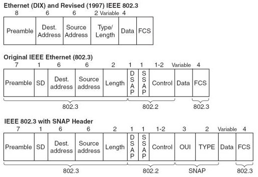
The experimental Ethernet described in that paper ran at 3 Mbps, and had 8-bit destination and source address fields, so Ethernet addresses were not the global addresses they are today. By software convention, the 16 bits after the destination and source address fields were a packet type field, but, as the paper says, "different protocols use disjoint sets of packet types", so those were packet types within a given protocol, rather than the packet type in current Ethernet which specifies the protocol being used.

Metcalfe left Xerox in 1979 to promote the use of personal computers and local area networks (LANs), forming 3Com. He convinced DEC, Intel, and Xerox to work together to promote Ethernet as a standard, the so-called "DIX" standard, for "Digital/Intel/Xerox"; it standardized the 10 megabits/second Ethernet, with 48-bit destination and source addresses and a global 16-bit type field. The standard was first published on September 30, 1980. It competed with two largely proprietary systems, token ring and ARCNET, but those soon found themselves buried under a tidal wave of Ethernet products. In the process, 3Com became a major company.

Twisted-pair Ethernet systems have been developed since the mid-80s, beginning with StarLAN, but becoming widely known with 10BASE-T. These systems replaced the coaxial cable on which early Ethernets were deployed with a system of hubs linked with unshielded twisted pair (UTP), ultimately replacing the CSMA/CD scheme in favor of a switched full duplex system offering higher performance.

Friday, February 6, 2009

NT1s and TAs for ISDN

ISDN lines need NT1s and terminal adapters (TAs) to make them compatible with the public network and customer equipment. The network termination type 1 (NT1) provides the electrical and physical connections to the carrier's network. On BRI ISDN (Basic Rate Interface Integrated Digital Services Network) services, NT1 devices change the ISDN circuit from 2 wires that come into the building from the CO to the 4 wires needed by ISDN equipment. In addition, the NT1 provides a point for line monitoring and maintenance functions.


In the US, the FCC requires that the customer be responsible for supplying NT1. In the rest of the world, telephone carriers supply the NT1.


Terminal adapters (TAs) perform the multiplexing and signaling function on ISDN services. Multiplexing enables one line to be used simultaneously for multiple voice or data calls. NT1s and TAs are often built into videoconferencing equipment and routers.

Thursday, February 5, 2009

PBX's with PRI Trunks

PBXs are used with PRI lines for the following:

Call centers, to receive the telephone numbers of callers

Individual telephone users for call screening

One voice mail system to support multiple PBXs

Dial-up videoconferencing

Large call centers use PRI ISDN to receive the telephone number of the person calling. With ISDN, the telephone number is sent at the same time as the call. However, it is sent on the separate D, or signaling channel. This is significant because it enables the telephone system, the PBX, to treat the telephone number information differently than the call. It can send the telephone number to a database that matches the number to the customer account number. The data network sends the account number to the agent's terminal that the call is sent to. It saves agents time by eliminating the need to key in account numbers.


Many corporation use PRI ISDN for incoming voice traffic. They local telephone company sends the caller's name and phone number over the signaling channel. The telephone system captures the information and sends it to the display-equipped telephone (the phones that are in most offices). Employees can use ISDN to screen calls. Unanswered calls are forwarded automatically into voice mail.

PRI ISDN private lines that connect PBXs together enable one voice mail system to be shared between multiple sites. The D channel carries voice mail signals that identify mailbox numbers and instructions to turn message-waiting indicators on or off. It also enables broadcast lists to be made up of users at different sites.

Companies with multiple PRI trunks can share the 24th signaling channel among a group of PRI trunks via nonfacility-associated signaling (NFAS). For example, an organization with 6 PRI trunks might have 4 of them equipped with 24 channels for voice and data. Two of the 6 would have 23 channels for user data and one signaling channel each with NFAS to support all 6 PRI trunks. Having 2 PRI circuits with signaling provides a backup in case one signaling channel fails. PRI lines do not work without a signaling channel.

Wednesday, February 4, 2009

Primary Rate Interface (PRI)

PRI has 24 64-kb channels in the US and Japan and 30 elsewhere in the world. PRI lines are similar to T-1 in that they both have 24 channels. However, PRI ISDN has out-of band signaling on the 24th channel. This is different from T-1 circuits, in which signaling is carried in-band, along with voice or data on each channel. On data communications, the signaling channel leaves each of the bearer channels "clear" capacity for all 64,000 bits. PRI does not require any bearer channel capacity for signaling such as call setup or teardown of signals.


PRI is used with PBXs, key systems and routers for incoming and outgoing voice and data. It is also used by ISPs (Internet Service Providers) and CLECs (Competitve Local Exchange Carrier) for dial-in modem Internet access. Each PRI supports 23 rack-mounted modems. The signaling channel carries the customer telephone number and the type of modem used. This provides billing and routing information. Moreover, the modems can handle ISDN as well as analog modem traffic.


BRI and PRI ISDN can communicate with each other for data such as videoconferencing and voice. PRI as will as BRI can make and receive voice calls to any device on the PSTN.

Tuesday, February 3, 2009

BRI ISDN Uses

The most common uses for BRI ISDN (Basic Rate Interface Integrated Services Digial Network) in the US are for dial backup for FR (Flat Rate Service) and for videoconferencing. BRI consists of two bearer channels for customer voice or data at 64 kbps. In addition, it has one 16 kbps signaling channel. It runs over a single pair or twisted wires between the customer and the telephone company.

Deployment of BRI ISDN is higher in Europe and Japan than in the US, where it never reached more than 1% penetration. It was complex to install, telephone companies charged usage fees for ISDN data calls, and the initial lack of widespread availability greatly hindered acceptance of ISDN, particularly among consumers.

France, Germany, Japan, and Switzerland are widely acknowledged to have a large base of BRI ISDN customers. In Europe, BRI ISDN is sometimes referred to as ISDN 2 because it has two bearer channels. Consumers in these countries use it for voice calls and Internet access. The absence of flat-rate pricing on switched services made per-unit charges for dial-up Internet access more acceptable.

Because prices of BRI lines are low compared to PRI (Primary Rate Interface with 24-channel) service, many enterprises use BRI for videoconferencing. To achieve adequate speed for acceptable quality, they bond 3 or 4 BRI circuits together. Bonding is the combination of multiple lines to increase bandwidth. For example, bonding the two bearer channels provides 128 kb of speed (2 x 64). Most organizations bond 3 or 4 circuits together for acceptable video quality at 384 kbps (3 x 128) or 512 kbps (4 x 128).

In bonded circuits, the signaling channel sends bits from each bearer channel sequentially on the ISDN circuits. People viewing the video see a continuous stream of images. To initiate the calls, the video equipment dials the telephone numbers at the remote BRI-equipped video system. Telephone companies charge per-minute fees for these video calls. The conference is ended when one party hangs up. Because it is a switched service, organization are not limited to having video calls to sites on their private networks.

Another application for BRI ISDN is backup access to FR networks in case the dedicated access line for the FR network fails. In these applications, the router usually automatically dials into the FR network when it senses that the dedicated access line is down. On data services, BRI equipment is required at both ends of the call. However, BRI-equipped voice services can call anyone on the PSTN. ISDN is not required at each end of voice calls.

Monday, February 2, 2009

ISDN

Integrated Services Digital Network is a worldwide public standard for sending voice, video, data or packets over the PSTN in a digital format. There are 2 flavors - Basic Rate Interface (BRI) and Primary Rate Interface (PRI) - which we will learn more about this week. It is important to note that manufacturers implemented some forms of ISDN differently from each other. This resulted in some incompatibilities between ISDN in Europe, North America and Japan.

ISDN is used mainly in enterprise call centers, connections from businesses to local and long distance telephone companies, and videoconferencing. PRI and BRI ISDN use out-of-band signaling to carry dialed digits, caller identification, dial tone and other signals. ISDN works over existing copper wiring, fiber or satellite media.