Last WotD we mentioned MiFi’s ability to support EvDO and UMTS/HSDPA 3G technologies. We will explore these further to gain an understanding of what exactly MiFi is able to offer current users.
EvDO (Evolution Data Optimized [or Only]): a newer wireless telecommunications technology that provides wireless data connections that are 300,000 to 600,000 bits per second – as much as 10 times as fast as a regular dial-up modem. Proponents say EvDO offers huge advantages over WiFi. EvDO can work over existing cell phone networks. One of the biggest barriers to EvDO is that it requires wireless companies to set aside a slice of their valuable airwaves just to transmit data. Because mobile phone companies barely have enough room to handle their voice traffic, EvDO is likely to remain on the back burner until the firms can acquire more spectrum. EvDO is a CDMA 2000 technology and implements various multiplexing techniques such as Code Division Multiple Access (CDMA) as well as Time Division Multiple Access (TDMA) to maximize user throughput and overall system throughput. EvDO is commonly spelled as Ev-DO and EV-DO.
Some Major Carriers Offering EvDO:
- Alltel
- Cricket
- LG Telecom (Korea)
- Metro PCS
- SK Telecom (South Korea)
- Sprint (branded as ‘Power Vision’ and ‘Mobile Broadband’
- U.S. Cellular
- Verizon Wireless (often branded as ‘Mobile Broadband’ and ‘VCAST’)
- Virgin Mobile
Tuesday, September 1, 2009
Wednesday, August 26, 2009
MiFi
MiFi: Developed by Novatel, a portable broadband wireless device typically the size of a credit card that combines functions of a modem, router and access point. Designed to simplify setting up a small local area network (LAN) a MiFi hotspot is a device that connects to a cellular 3G network and bridges the network to Wi-Fi devices (up to 10m/30ft distance). This creates a local “cloud” of high-speed Internet connectivity that can be shared between users and Wi-Fi devices such as laptops, cameras, gaming devices, and multimedia players. The device can be connected to a computer via a MicroUSB connection, though doing so disables the wireless feature. In the U.S., MiFi devices are available from Verizon Wireless (MIFI 2200) and Sprint (MIFI 2200).
Below is a list of some of MiFi’s other featuers:
- Storage capacity.
- The ability to host applications.
- Supports EV-DO or UMTS/HSDPA 3G technologies.
- Internal battery offers four hours active use, forty hours standby before it needs to be recharged.
- Can be configured for automatic email synching and virtual private network (VPN) connection.
- Supports remote management.
Source: http://whatis.techtarget.com/definition/mifi.html

Pic: http://www.3g.co.uk/PR/Dec2008/First_MiFi_Intelligent_Mobile_Hotspot.jpg
Tuesday, August 18, 2009
In-Home BPL
Another form of Broadband over Powerline (BPL) is:
In-House BPL: a form of indoor PLC (Powerline Carrier) that operates over residential or business interior electrical cabling at 110/220 volts. Standards for in-house PLC are relatively recent, with the HomePlug standards perhaps being the most notable. HomePlug 1.0 was published in 2001 by the HomePlug Powerline Alliance (http://www.homeplug.org/), which was founded by vendors including Cisco and Intel. Those standards are loosely based on Ethernet and support up to 16 devices communicating at speeds up to 14 Mbps over a shared electrical path. HomePlug compatible devices (e.g., include Pcs, routers and bridges that use Ethernet, USB or Wi-Fi technologies) can simply plug into an electrical socket through a bridge or adapter about the size of a typical voltage adapter and, thereby, connect directly to the LV wiring. So every electrical socket effectively becomes a port into a high speed LAN. In-House BPL speeds don’t compare well with more conventional Ethernet LANs, but can be an attractive solution where buildings can’t easily be rewired and where a building’s physical layout is not conducive to wireless LANs. The next step is the HomePlug AV standard, which is being built from the group up to support entertainment applications such as HDTV and Home Theater. HomePlug AV will run at speeds up to 200 Mbps. Dozens of HomePlug 1.0 compatible products have been certified and many more are under development. In a home a BPL modem plugs into a wall outlet inside the house, receives those signals from the outside power lines and typically converts them into a familiar 802.11b Ethernet connection.
Pictured below: Illustration of how a BPL modem used in a home

Tuesday, August 11, 2009
Access BPL
We left off last time with Broadband over Powerline (BPL) discussing home voice/data traffic is able to be transmitted via electrical utility power lines. Today we will discuss one form of this technology.
Access BPL: a form of PLC (Powerline Carrier) that uses components of the existing electrical power grid for the delivery of broadband services. Specifically, Access BPL uses special injectors (i.e. modems and couplers) to interface the telecommunications network to medium voltage (MV) lines in the electrical distribution network. MV operates at a manageable 7,200 volts or so. The Radio Frequency carrier supporting the communications signals shares the same line with the electrical signals as they operate at different frequencies. Repeaters spaced every 300 meters or so serve to re-amplify, re-time and regenerate the signal as it travels from the utility substation toward the customer premises. The signals are removed by extractors placed just ahead of the transformers, which typically serve a number of households. Typically, the extractors bypass the transformers and bridge the communications signals between the MV lines and the low voltage (LV) (110/220 volts) drops to the premises. Alternatively, they may bridge the signal to a Wi-Fi (802.11 b/g) node that serves multiple premises through a wireless hotspot. Although Access BPL services are not widely available, a small number of utilities began offering service in 2003 and 2004, and several others have announced their intentions to do so.
In summary, there are 3 components to Access BPL:
1) Medium voltage line (MV)
2) Bypass of the low-voltage transformer in residential neighborhoods that steps down voltage
3) Low voltage distribution from the transformer to residential electrical outlets
Overall, this could be a great “last mile” alternative to DSL and Cable access when speaking in terms of delivering connectivity to rural subscribers.

Source: http://www.ic.gc.ca/eic/site/smt-gst.nsf/vwimages/bplf1e.jpg/$file/bplf1e.jpg
Access BPL: a form of PLC (Powerline Carrier) that uses components of the existing electrical power grid for the delivery of broadband services. Specifically, Access BPL uses special injectors (i.e. modems and couplers) to interface the telecommunications network to medium voltage (MV) lines in the electrical distribution network. MV operates at a manageable 7,200 volts or so. The Radio Frequency carrier supporting the communications signals shares the same line with the electrical signals as they operate at different frequencies. Repeaters spaced every 300 meters or so serve to re-amplify, re-time and regenerate the signal as it travels from the utility substation toward the customer premises. The signals are removed by extractors placed just ahead of the transformers, which typically serve a number of households. Typically, the extractors bypass the transformers and bridge the communications signals between the MV lines and the low voltage (LV) (110/220 volts) drops to the premises. Alternatively, they may bridge the signal to a Wi-Fi (802.11 b/g) node that serves multiple premises through a wireless hotspot. Although Access BPL services are not widely available, a small number of utilities began offering service in 2003 and 2004, and several others have announced their intentions to do so.
In summary, there are 3 components to Access BPL:
1) Medium voltage line (MV)
2) Bypass of the low-voltage transformer in residential neighborhoods that steps down voltage
3) Low voltage distribution from the transformer to residential electrical outlets
Overall, this could be a great “last mile” alternative to DSL and Cable access when speaking in terms of delivering connectivity to rural subscribers.
Source: http://www.ic.gc.ca/eic/site/smt-gst.nsf/vwimages/bplf1e.jpg/$file/bplf1e.jpg
Wednesday, August 5, 2009
Broadband over Powerline (BPL)
In the News Today:
Since the federal government as set aside an estimated $7.2 Billion in funding to bring broadband to underserved areas, telecom companies are rushing to meet the August 14th deadline to apply. 1 company in particular, International Broadband Electric Communications (IBEC) located in Huntsville, Alabama is hoping to secure a piece of this funding to further push their technology offering known as Broadband over Powerline or “BPL”. Today we will discuss further what BPL entails and how, although it is a viable technology, it’s very expensive to implement and maintain.
For more information on how companies are responding to the August 14th application deadline for part of the money granted by American Recovery & Reinvestment Act of 2009, check out the following URL:
http://www.msnbc.msn.com/id/32284073/ns/business-businessweekcom/#storyContinued
Broadband over Powerline (BPL): the contemporary and updated version of Powerline Carrier (PLC), a means for sending and receiving voice and data over electric utility power lines. PLC has been used for many years by electric utilities for low speed data communications applications such as telemetry and control between power plants and substations. PLC also has long been used by telephone companies to provide voice service to extremely remote subscribers who have electric service but for whom the construction costs associated with telco local loops would be prohibitively expensive. BPL can be broken into two component technologies: Access BPL and In-House BPL
We will continue to explore these technologies throughout the week…for now, refer to the below illustration for a reference on how BPL delivers voice/data to households
 Source: http://cache.gizmodo.com/assets/resources/2007/08/diagram2.gif
Since the federal government as set aside an estimated $7.2 Billion in funding to bring broadband to underserved areas, telecom companies are rushing to meet the August 14th deadline to apply. 1 company in particular, International Broadband Electric Communications (IBEC) located in Huntsville, Alabama is hoping to secure a piece of this funding to further push their technology offering known as Broadband over Powerline or “BPL”. Today we will discuss further what BPL entails and how, although it is a viable technology, it’s very expensive to implement and maintain.
For more information on how companies are responding to the August 14th application deadline for part of the money granted by American Recovery & Reinvestment Act of 2009, check out the following URL:
http://www.msnbc.msn.com/id/32284073/ns/business-businessweekcom/#storyContinued
Broadband over Powerline (BPL): the contemporary and updated version of Powerline Carrier (PLC), a means for sending and receiving voice and data over electric utility power lines. PLC has been used for many years by electric utilities for low speed data communications applications such as telemetry and control between power plants and substations. PLC also has long been used by telephone companies to provide voice service to extremely remote subscribers who have electric service but for whom the construction costs associated with telco local loops would be prohibitively expensive. BPL can be broken into two component technologies: Access BPL and In-House BPL
We will continue to explore these technologies throughout the week…for now, refer to the below illustration for a reference on how BPL delivers voice/data to households
Source: http://cache.gizmodo.com/assets/resources/2007/08/diagram2.gif
Friday, July 31, 2009
Mobile Communications (story)
A small entertaining bit about the origins of “mobile” technology….
Mobile communications: Quite simply, the ability to communicate while moving. Wireless technologies like cordless telephony and cellular allow you to communicate on the go. Wired technologies, like copper wire and fiber optics, don’t work if you might break the wire, or run out of wire. One of the great stories about mobile communications involves wires.
According to William E. Kennard, FCC Chairman, and as included in a speech he made in 1998, the U.S. military faced a problem in 1907. The cavalry needed to communicate when on patrol. So, one horse solider would ride behind the troops, unreeling wire along the ground. When a message needed to be sent back to the base camp, the soldier would jump off his horse, plant a metal stake in the ground, and send a message via Morse code. This process slowed the progress of the troop. Military engineers came up with a solution. They put a copper patch on the horse’s skin! Since a horse always has one hoof on the ground, the circuit was complete! Therefore, the scouts could send a message while riding. (No mention was made of the effect on the horse)
Tuesday, July 21, 2009
Mobile Virtual Network operator Enabler (MVNE)
Last week we ended with discussing MVNO’s (Mobile Virtual Network Operators). Today we will take a look a what constitutes an MVNE.
MVNE (Mobile Virtual Network operator Enabler): a company that “enables” MVNO’s. In order to “enable” an MVNO, the enabler builds a service platform, which provides billing, care, logistics, and carrier interfaces. By contrast, Richard Branson’s Virgin Mobile, probably the most successful MVNO to date, has built out their own infrastructure, at a cost estimated to be $40-50 millions. It took them more than two years to get to market by going this route. An enabler, or MVNE, builds out a shared platform, which is offered to multiple MVNOs, thus allowing them to avoid the huge capital cost of building out their own infrastructure and at the same time, getting them to market faster. An MVNO enabled by an MVNE can get to market in as little as three or four months at a cost of a few million, depending on how complex/feature-laden their offerings are.
For more information visit: http://www.mobilein.com/MVNE_White_Paper.pdf
Friday, July 17, 2009
Mobile Virtual Network Operator (MVNO)
In recent news, Comcast became the first cable MVNO (Mobile Virtual Network Operator) in the U.S. to offer high-speed WiMax services announcing “Comcast High-Speed 2go”.
http://www.wimax.com/commentary/blog/blog-2009/june-2009/comcast-launches-first-wimax-market-0630
MVNO (Mobile Virtual Network Operator): an organization that buys minutes and services wholesale from an existing carrier (or carriers) and resells them under its own brand. Under GSM, for example, it may issue its own SIM card. A MVNO is basically a reseller. It does not have radio frequency (spectrum) nor does it have its own communications plant. It usually has its own billing system, however. A company that does have its own frequency allocation is simply known as a Mobile Network Operator (MNO). Any of the wireless technologies used on the existing network can be used by the MVNO (e.g. CDMA, GSM, UMTS, etc)
Examples of MVNO’s:
- Boost Mobile
- Mobile PCS
- Virgin Mobile
MVNO’s are typically autonomous entities that works independently of the MNO, giving it the ability to set its own pricing structure, subject to the rates of the network operator. Some MVNO’s run their own Billing and Customer Care solutions known as BSS (Business Support Systems). However, many use a MVNE (Mobile Virtual Network operator Enabler) which we will discuss on Monday.
Wednesday, July 15, 2009
WiMax
Today we will talk about WiMax. In the next WotD we will differentiate between 4G and WiMax as these 2 terms seem to be synonymous when coming up in conversation and it’s important to know the difference between the two (as well as how they are related).
WiMax: Worldwide Interoperability for Microwave Access, is a Broadband Wireless Access (BWA) solution that is based on standards recommendations from both the IEEE 802.16 working group and the ETSI (European Telecommunications Standards Institute). WiMax is promoted by the WiMax Forum, a special interest group comprising members of the manufacturing, carrier and service provider communities. The IEEE established the 802.16 working group to standardize Local Multipoint Distribution Services (LMDS) and Multichannel Multipoint Distribution Services (MMDS).
There are 2 types of WiMax:
1) Fixed WiMax (no support for mobility)
2) Mobile WiMax
Various uses of WiMax include:
· Connecting Wi-Fi hotspots to the Internet.
· Providing a wireless alternative to cable and DSL for "last mile" broadband access.
· Providing data and telecommunications services.
· Providing a source of Internet connectivity as part of a business continuity plan. That is, if a business has both a fixed and a wireless Internet connection, especially from unrelated providers, they are unlikely to be affected by the same service outage.
· Providing portable connectivity.
· WiMax applications include private campus networks, T-1 and Fractional T-1 business service, rural or developing areas where cabled broadband service is not available, Wi-Fi hotspot backhaul and disaster recovery (as demonstrated during Hurricane Katrina).
Sources: http://en.wikipedia.org/wiki/WiMAX;
Newton’s Telecom Dictionary, 22nd Edition; 2006
Companies and WiMax:
Companies have been investigating the use of WiMax to target the “last mile” broadband access for rural communities where broadband access was previously economically unviable. This would help open up new potential wireless markets and help compete with cable/DSL offerings for Internet service. Other significant movements in the wireless industry include:
- In 2006, Sprint announced its intent to invest $5 Billion into WiMax
- In 2007, WiMax base stations quadrupled from 5,000 to 20,000 globally
- In 2008, a new company, Clearwire, (now with Sprint owning a majority share of the company at 51%) was formed by the aggregation of 120Mhz of spectrum owned by various companies in the hopes to benefit from combined service offerings and network resources (with the intent that cable companies are able to provide content using the network as a MVNO: Mobile Virtual Network Operator)
- As of June 2009, there were roughly 475 deployments of WiMax in 140 countries reaching nearly 430 million people worldwide (numbers include planned, in-process and commercialized networks)
- Looking beyond 2009, Verizon Wireless (along with MetroPCS Wireless and U.S. Cellular) will be the lead network operator touting the LTE standard for 4G (competing alongside Sprint’s WiMax offering)
Source: http://www.itbusinessedge.com/cm/community/features/articles/blog/lte-versus-wimax-moves-from-theoretical-to-real/?cs=34099
Monday, July 13, 2009
MIMO (Multiple Input/Multiple Output) **4G Technology**
*Another technology/technique involved in 4G communications
MIMO (Multiple Input/Multiple Output): MIMO is a wireless technology that employs multiple intelligent input and output radio antennas to improve transmission speed and quality over longer distances than otherwise possible. The technique involves Space Division Multiplexing (SDM), with arrays of multiple spatially separated transmit and receive antennas. The idea is to push 802.11 (also known as Wi-Fi) WLAN (Wireless Local Area Network) transmission rates from around 20 Mbps to at least 100 Mbps and perhaps as high as 540 Mbps. MIMO also will extend 802.11 distances from 100 meters to as much as 200 meters. MIMO is the basis for the developing IEEE 802.11n standard and promotes spectral efficiency during 4G communications. MIMO is typically combined with OFDM (Orthogonoal Frequency-Division Multiplexing) to achieve an even greater level of spectral efficiency.
MIMO (Multiple Input/Multiple Output): MIMO is a wireless technology that employs multiple intelligent input and output radio antennas to improve transmission speed and quality over longer distances than otherwise possible. The technique involves Space Division Multiplexing (SDM), with arrays of multiple spatially separated transmit and receive antennas. The idea is to push 802.11 (also known as Wi-Fi) WLAN (Wireless Local Area Network) transmission rates from around 20 Mbps to at least 100 Mbps and perhaps as high as 540 Mbps. MIMO also will extend 802.11 distances from 100 meters to as much as 200 meters. MIMO is the basis for the developing IEEE 802.11n standard and promotes spectral efficiency during 4G communications. MIMO is typically combined with OFDM (Orthogonoal Frequency-Division Multiplexing) to achieve an even greater level of spectral efficiency.
Thursday, July 9, 2009
OFDM (Orthogonal Frequency Division Multiplexing) **4G technology**
In the next few WotD’s we’ll take a look at the principal technologies that comprise 4G…
OFDM (Orthogonal Frequency Division Multiplexing): A modulation technique for wireless communications, OFDM was patented by Bell Labs in 1970, and initially was used in a naval communications system dubbed ‘Catherine’. Much like DMT (Discrete MultiTone), OFDM splits the datastream into multiple RF (Radio Frequency) channels, each of which is sent over a subcarrier frequency. DMT and other more conventional techniques encode data symbols for a given data stream onto one radio frequency. In an OFDM system, however, each tone (i.e., frequency) is orthogonal (i.e., independent or unrelated) to the other tones; multiple data symbols are encoded concurrently onto multiple tones in a parallel fashion. The signal-to-noise ratio of each of those very precisely defined frequencies is carefully monitored to ensure maximum performance. OFDM eliminates the requirement for guard bands to separate the frequencies and, thereby, avoid interference from adjacent RF channels. Guard bands are required only around the edges of a set of tones, i.e., RF channels. This yields greater spectral efficiency, as virtually all of the allocated RF spectrum can be used for data transmission.
OFDM is used by the HomePlug Powerline alliance to avoid line noise in a residential power-line network. How it works:
1. Broadband content from cable modem, DSL or satellite is fed to home gateway
2. By plugging gateway into any electrical outlet, content is bridged to any HomePlug-enabled device
3. OFDM takes multiple signals of different frequencies and combines them to form one signal to avoid line “noise”
4. HomePlug network monitors power lines for “noise”.
For more on HomePlug visit their website: http://www.homeplug.org/home
If noise occurs on a particular frequency, OFDM engine shifts transmission to another frequency. OFDM also is used in the IEEE 802.16 WLL specification, also known as WiMax.
Wednesday, July 8, 2009
4G Mobile Network
4G Mobile Network: 4G is what the next, next generation cellular might be. The idea is simple – universal high-speed Internet access. The thinking is WiFi Internet access (at up to 10 megabits per second) with blanket coverage and fewer base stations than are needed in today’s cell phone networks. Firms including IPWireless, Flarion, Navini, ArrayComm and Broadstorm offer just such a blend. But these are proprietary solutions, so far. Such proposed 4G wireless-broadband systems can be seen in two ways: as a rival to coffee shop WiFi or as a wireless alternative to the cable modem and digital subscriber line (DSL) technologies that now provide broadband access to homes and offices. IPWireless sees their system as a fast internet connection that follows you around. Navini calls it “nomadic broadband”; ArrayComm’s term is “personal broadband”.
Mike Gallagher of Flarion, a firm backed by Cisco, likens WiFi to cordless phones that work within a limited range of a base-station whereas 4G is akin to mobile phones that work anywhere. Advocates of 4G technology argue that, unlike with 3G and WiFi, the business case for 4G is sound. Nobody is sure how commercial WiFi hotspots will make money. The number of connections per day at most hotspots is still tiny. But 4G is being priced like fixed-line broadband, a service for which millions of users worldwide are already willing to pay about $50 a month. 4G networks may be built initially in regions where cable and DSL are unavailable, in order to capitalize on pent-up demand for broadband. Some cell phone companies are said to be considering skipping 3G altogether in favor of 4G.
Source: Newton’s Telecom Dictionary, 2nd Edition; 2006
*4G Developments*
NTT DoCoMo has been testing a 4G system prototype with 4x4 MIMO called “VSF-OFCDM” at 100 MB/sec while moving and 1GB/sec while stationary and is planning on releasing the first commercial network in 2010.
Digiweb, an Irish fixed and wireless broadband company, announced that they have received license from ComReg (Irish Telecom regulator) for the provisioning of 4G mobile communications.
Verizon Wireless announced in September 2007 that it’s planning a joint effort with Vodafone to transition its networks to the 4G standard LTE. In December 2008, Verizon Wireless announced that they intend to build, design, and begin to roll out a LTE network by the end of 2009.
Sprint announced the offering of a 3G/4G connection plan (which is currently only available in Baltimore).
Source: http://en.wikipedia.org/wiki/4G
More on 4G, pervasive networks, and mesh routing to come…stay tuned!
Tuesday, July 7, 2009
HSDPA (in W-CDMA)
HSDPA (in W-CDMA): High Speed Downlink Packet Access (HSDPA) is a packet-based data service in W-CDMA downlink with data transmission up to 8-10 Mbps (and 20 Mbps for MMO systems) over a 5MHz bandwidth in WCDMA downlink. HSDPA implementations includes Adaptive Modulation and Coding (AMC), Multiple-Input Multiple-Output (MIMO), Hybrid Automatic Request (HARQ), fast cell search, and advanced receiver design. In 3rd generation partnership project (3GPP) standards, Release 4 specifications provide efficient IP support enabling provision of services through an all-IP core network and Release 5 specifications focus on HSDPA to provide data rates up to approximately 10 Mbps to support pack-based multimedia services. MIMO systems are the work item in Release 6 specifications, which will support even high data transmission rates up to 20 Mbps. HSDPA is evolved from and backward compatible with Release 99 WCDMA systems.
Monday, July 6, 2009
3.5G Mobile Network
3.5G Mobile Network: a faster version of 3G wireless networks, 3.5G uses a technology called HSDPA, which is a significant enhancement to W-CDMA and can achieve speeds of up to 14.4 Mbps. HSDPA stands for High Speed Downlink Packet Access. It is a packet based data service feature of the WCDMA standard which provides a downlink with data transmission up to 8-10 Mbps (and 20 Mbps for MIMO systems) over a 5MHz bandwidth in WCDMA downlink. The high speeds of HSDPA is achieved through techniques including; 16 Quadrature Amplitude Modulation, variable error coding, and incremental redundancy. HSDPA is a technology upgrade to current UMTS networks.
Friday, July 3, 2009
3G Mobile Network
Third Generation Mobile System. Most commonly 3G networks are discussed as graceful enhancements of the GSM cellular standards. Thereby, existing GSM networks can be upgraded on a non-disruptive basis. The enhancements include greater bandwidth, more sophisticated compression techniques, and the inclusion of in-building systems. 3G networks will transmit data at 144 kilobits per second, or up to 2 megabits per second from fixed locations. This planned evolution of GSM is an integral part of the ITU-T’s vision of IMT-2000 (International Mobile Telecommunications for the year 2000), which clearly missed the target date of 2000. The aim of IMT-2000 is to harmonize worldwide 3G systems to provide global roaming.
3G has standardized (or will) three mutually incompatible standards: FDD, TDD, and CDMA2000. FDD and TDD are extensions of GSM architecture using CDMA technology in the air interface. CDMA2000 is the extension of IS95 air interface for wideband data applications. The three standards will compete with each other in the marketplace. In addition to the technical differences between the standards, there is a strong political background in the competition. FDD and TDD were proposed by European firms, and will be promoted worldwide as the heirs to GSM systems. CDMA2000 was the standard championed by Qualcomm, the USA based company with many patents in CDMA technology.
We will go into more detail on 3G in the upcoming WotD posts. Enjoy the holiday!
Wednesday, July 1, 2009
2.5G and GPRS
2.5G Mobile Network: Second-and-a-half generation wireless. Refers to the additional features and functionality added to digital cellular phones, such as Internet access and messaging. The main feature added to 2.5G is GPRS, a mobile data communications service running at the speed of a dial-up landline.
GPRS: Want to connect your laptop to your cell phone and surf the web or send emails? GPRS is for you. GPRS stands for General Packet Radio Service. And it’s the always-on packet data service for GSM, which is the cell phone standard which most countries of the world use, including Europe, Australia, America (not all carriers obviously) and some parts of Asia. The idea is that you’ll connect your GPRS-equipped (also called 2.5G) cell phone to your laptop with a cable or insert a small GPRS-equipped PCMCIA card into your laptop and transmit. GPRS will be most useful for “bursty” data applications such as mobile Internet browsing and e-mail. GPRS has been demonstrated as fast as 115 Kbps. And in theory it can go that fast. But the reality is that you’ll get between 20Kbps and 50Kbps throughput—about the speed you get from your dial-up home landline.
One big advantage of GPRS is that it’s “always on” just like your DSL line, your cable modem or your office network. To send a data message you won’t have to waste a minute dialing a number and listening to the modems go through their interminable screeching/connection “dance”. GPRS is the primary feature of what has become known as 2.5G – the upgrade to today’s 2G cell phone network. 1XRTT is the CDMA equivalent of GPRS.
Source: Newton’s Telecom Dictionary 22nd edition; 2006
Tuesday, June 30, 2009
2G Mobile Network (PCS, and 2G+)
2G Mobile Network: Second generation mobile network. Refers to the second generation cellular phones that introduced digital technology and carried both voice and data conversations.
Examples of 2G mobile networks:
- CDMA
- TDMA
- GSM (accounts for over 80% of all subscribers around the world!)
2G services are more commonly referred to as Personal Communications Service (PCS in the United States). PCS operates at 1900Mhz. The FCC set aside the frequency between 1850 and 1990 MHz for mobile phone use in 1994 as the original cellular phone band (824 – 894 MHz) was becoming overcrowded. Dual band GSM phones are capable of working in both 850 and 1900 Mhz bands while tri-band or quad-band phones operate in 3 or 4 different frequency bands. While GSM is used throughout the world, CDMA and TDMA are used primarily in the Americas, with PCS being referred to as GSM-1900 outside of the US and in Hong Kong specifically as GSM-1800.
Sources: Newton’s Telecom Dictionary, 22nd edition; 2006 http://en.wikipedia.org/wiki/Personal_Communications_Service
2G+ Mobile Network: Second generation plus mobile network. Refers generically to a category of mobile wireless networks that support higher data rates than 2G mobile networks.
Example of 2G+ mobile network:
- GPRS
Monday, June 22, 2009
1G Mobile Network
First generation mobile network that refers to the initial mobile wireless networks using analog technology only and not carrying data. Advanced Mobile Phone Service (AMPS) is an example of a 1G mobile network standard. Although 1G and 2G both use digital signaling to connect radio towers to the rest of the telephone system, the voice itself is encoded to digital signals in 2G whereas 1G is only modulated to higher frequency (~150 Mhz).
Other 1G standards (other than AMPS) are NMT (Nordic Mobile Telephone) which is used in Nordic countries, Eastern Europe and Russia; TACS (Total Access Communications System) used in the United Kingdom and JTAGS used in Japan. Keep in mind that analog cellular service is quickly being phased out in most places worldwide.
Sources: Newton’s Telecom Dictionary 22nd edition, 2006; http://www.javvin.com/wireless/1G.html
Tuesday, June 16, 2009
Location Services (re-cap)
Location Services (re-cap):
Over the past few weeks, we have covered many different applications of location services. Since we’ve gone through a wide array of definitions, I thought it would be helpful to summarize what we’ve touched upon over this time. The first group was classified as what we call “network solutions” (think triangulation) while the second group was considered “handset solutions” (think GPS). To summarize these last words of the day, I have divided the terms into the 2 groups to help conceptualize the offerings of location services.
Network Solutions:
- Angle of Arrival (AOA)
- Uplink Time Difference of Arrival (U-TDOA)
- Wireless Location Signatures
- Location Pattern Matching (LPM)
- Multi-path Fingerprinting (MP)
- Enhanced Cell Identity (E-CID)
Handset Solutions:
- GPS
- Assisted GPS (A-GPS)
- Wireless Assisted GPS (WAGPS)
- TV-GPS
- Advanced Forward Link Trilateration (A-FLT)
- Timing Advance/Network Measurement Report (TA/NMR)
- Enhanced Observed Time Difference (E-OTD)
Thursday, June 11, 2009
Enhanced Observed Time Difference (E-OTD)
Enhanced Observed Time Difference measures the differences in time that signals from the base stations take to reach both the handset and a fixed point in the network. This information is then sent from the handset and the fixed point to a mobile location center where a latitude and longitude are computed and sent to the PSAP. The main difference between GPS-location services and E-OTD is that GPS uses a constellation of satellites maintained by the U.S. department of defense, whereas E-OTD uses a mathematical algorithm to identify the location of the caller based on the time signal between base stations as well as a triangulation scheme. A major driver for E-OTD implementation in the U.S. was the E-911 mandate made by the FCC.

Image courtesy of Cambridge Position System
Source: http://www.mobileinfo.com/locationbasedservices/E_OTD.htm
Wednesday, June 10, 2009
Timing Advance/Network Measurement Report (TA/NMR)
This method relies in part on timing advance, which is the maximum amount of time that a TDMA mobile station uses to compensate for propagation delay in order to avoid user time slot overlap when the mobile is far away from the base station. It also employs information from the Network Management Report, which is the measurement done either at the handset or base stations to improve communication flow on the air interface. Various events – such as hand-off, power control, and candidates list – use the Network Management Report. Basically, the “timing advance” value is the length of time a signal from a mobile device takes to reach a particular base station. A TDMA frequency is shared between multiple users (employing TDMA) with each user transmitting periodically for less than 1/8 of the time within one of the eight timeslots. Since the users are various distances from the base station and radio waves travel at a finite speed (speed of light), the precise time at which the phone is allowed to transmit a burst of traffic within a timeslot must be adjust accordingly. Timing Advance (TA) is the variable controlling this adjustment.
Sources: Newton’s Telecom Dictionary 22nd edition 2006; http://en.wikipedia.org/wiki/Timing_advance
Sources: Newton’s Telecom Dictionary 22nd edition 2006; http://en.wikipedia.org/wiki/Timing_advance
Tuesday, June 9, 2009
Advanced Forward Link Trilateration (A-FLT)
A-FLT is a handset-based position location technology (primarily used on CDMA networks) that works by using measurements, taken by the handset, of signals from nearby base stations, and reporting the time/distance readings back to the network, which are then used to triangulate an approximate location of the handset. In general, at least three surrounding base stations are required to obtain an optimal position fix. Unlike GPS (or A-GPS), AFLT does not use GPS satellites to determine location but rather a time difference of arrival (TDOA) technique. TDMA (Time Division Multiple Access) is required to transmit location data and is commonly paired with A-GPS to form a “hybrid solution”; an alternative to purely “handset-based” or “network-based” location technologies. (As AFLT is well-suited for urban environments with close proximity of base stations whereas A-GPS is more advantageous in suburban and rural areas having low base-station densities)
Monday, June 8, 2009
Wireless Assisted GPS (WAG or waGPS)
Generally uses advanced chipsets capable of acquiring very weak GPS signals and integrating the signals very quickly to determine location. WAG distributes GPS functionality between a 1) GPS reference receiver, 2) Location Server, 3) and GPS-enabled client device. The Reference Receiver provides GPS data and precise time to the Location Server. The Location Server computes and provides aiding data to the client, and performs navigation solution upon receipt of GPS measurements from client. The client pre-processes and returns basic GPS measurements along with statistical measures that characterize the signal environment.
Source: http://www.w3.org/
*Bonus WotD: TV-GPS uses synchronization signals from television stations to determine handset location when indoors. Because of the frequency and power of TV signals, they often can be received at indoor locations where GPS signal cannot.
Source: http://www.w3.org/
*Bonus WotD: TV-GPS uses synchronization signals from television stations to determine handset location when indoors. Because of the frequency and power of TV signals, they often can be received at indoor locations where GPS signal cannot.
Thursday, June 4, 2009
GPS and A-GPS
Now that we’ve seen the network solutions for location services:
- Angle of Arrival (AOA)
- Uplink Time Difference of Arrival (U-TDOA)
- Wireless Location Signatures
- Location Pattern Matching (LPM)
- Multi-path Fingerprinting (MP)
- Enhanced Cell Identity (E-CID)
We can begin to focus on various handset solutions for location services.
GPS: GPS techniques use handsets equipped with GPS receivers. The GPS receiver determines the caller’s latitude and longitude which is sent to the provider’s receivers and relayed to the PSAP (Public Safety Access Point).
Assisted GPS: A-GPS uses techniques and advanced chipsets designed to allow reception of GPS signals indoors. Assisted GPS can be supplemented with an advanced forward link trilateration (A-FLT) system. A-FLT is a network-based location technology that takes measurements of signals from nearby base stations and reports time and distance readings back to the network, which uses them to triangulate an approximate location of the handset.
The benefits of A-GPS over standard GPS include but are not limited to:
· Faster location acquisition
· Less processing power is required by the device
· Saves battery life on your phone
· Location acquisition indoors or in non-optimal environmental settings
Source: http://www.wmexperts.com/articles/gps_vs_agps_a_quick_tutorial.html
*Note: In the picture below, you can see that the AGPS server actually offloads work from the phone/satellites so that most of the CPU and programming required for location identification is performed on the server itself.

Source: http://images.wmexperts.com/articleimages/2008/01/agps.jpg
- Angle of Arrival (AOA)
- Uplink Time Difference of Arrival (U-TDOA)
- Wireless Location Signatures
- Location Pattern Matching (LPM)
- Multi-path Fingerprinting (MP)
- Enhanced Cell Identity (E-CID)
We can begin to focus on various handset solutions for location services.
GPS: GPS techniques use handsets equipped with GPS receivers. The GPS receiver determines the caller’s latitude and longitude which is sent to the provider’s receivers and relayed to the PSAP (Public Safety Access Point).
Assisted GPS: A-GPS uses techniques and advanced chipsets designed to allow reception of GPS signals indoors. Assisted GPS can be supplemented with an advanced forward link trilateration (A-FLT) system. A-FLT is a network-based location technology that takes measurements of signals from nearby base stations and reports time and distance readings back to the network, which uses them to triangulate an approximate location of the handset.
The benefits of A-GPS over standard GPS include but are not limited to:
· Faster location acquisition
· Less processing power is required by the device
· Saves battery life on your phone
· Location acquisition indoors or in non-optimal environmental settings
Source: http://www.wmexperts.com/articles/gps_vs_agps_a_quick_tutorial.html
*Note: In the picture below, you can see that the AGPS server actually offloads work from the phone/satellites so that most of the CPU and programming required for location identification is performed on the server itself.
Source: http://images.wmexperts.com/articleimages/2008/01/agps.jpg
Wednesday, June 3, 2009
Enhanced Cell Identity (E-CID)
Enhanced Cell Identity uses a combination of angular information (the cell sector receiving the signal) and timing information to approximate the location of the handset. Similar to Cell Identification, E-CID fixes the location of the user by identifying which cell in a network is carrying the user’s call and translates that information into latitude and longitude. Best used in less dense spaces, E-CID is little more accurate than Cell ID but has the capability of extending to less serviced rural areas.
Tuesday, June 2, 2009
Multi-path Fingerprinting (MP)
This technology uses features of the physical environment to locate mobile handsets. A wireless signal bounces off a variety of solid objects on the way to its destination (either a base station antenna or a handset), causing what’s called multipath interference. Essentially, the same signal is received multiple times due to the delay caused by bouncing off objects and taking longer paths to the destination. Multipath Fingerprinting takes advantage of this characteristic (which is normally a nuisance) to characterize signals that are received from certain locations. For instance, a base station can record what a handset signal looks like transmitted from a certain intersection of highways. A block away, the multipath signal “fingerprint” will look different, since the location of buildings, trees, and other obstructions has changed. To employ this system, an operator must send test units around to various locations so the base stations can record the fingerprints and create a database for comparison later on. Of course, if new construction occurs in an area the fingerprint will change and must be re-recorded.
Friday, May 22, 2009
Location Pattern Matching (LPM)
The wireless phone’s signal is received at various antenna sites equipped with special gear. The receivers send the caller’s voice call to the mobile switch, where sophisticated equipment analyzes the acoustic radio signal, and then compares it to a database of standard signal characteristics. These characteristics include signal reflections (multipath), echoes and other signal “anomalies”. According to U.S. Wireless, the only supplier of gear for this technique, when a computerized match is made, the location of the caller can be determined within the FCC’s requirements. The technique is effective in urban environments that include tall buildings and other obstructions, where other techniques might not succeed. The caller’s voice call and the latitude and longitude are then sent to the PSAP for use by the dispatcher. LPM works with any phone – digital, analog, TDMA, GSM, CDMA, etc.

Source: http://www.911dispatch.com/911/lpm.gif
Source: http://www.911dispatch.com/911/lpm.gif
Thursday, May 21, 2009
Wireless Location Signatures
These methods compare the radio signal received to a database of standard signal characteristics, such as reflections and echoes. Using this information from several cell site receivers, the caller location can be computed and sent to the PSAP. This technique works best in urban environments where lots of structures exist to provide the needed reflections. It works with any phone – digital, analog, TDMA, GSM, CDMA, etc.
A key player in the field of Wireless Location Signatures (WLS) is Polaris Wireless. To learn more about their WLS offerings, check out http://www.polariswireless.com/our-technology
A key player in the field of Wireless Location Signatures (WLS) is Polaris Wireless. To learn more about their WLS offerings, check out http://www.polariswireless.com/our-technology
Tuesday, May 19, 2009
Uplink Time Difference of Arrival (U-TDOA)
This is sometimes referred to simply as Time Difference of Arrival (TDOA). Time Difference of Arrival relies on the fact that each cell site is generally a different distance from the caller and that signals travel with constant velocity. Therefore, each signal arrives at the cell site at slightly different times. Using these properties, a signal defines a locus of points on a circle around a base station on which a mobile could be located. Then, using synchronized receivers, the times can be compared and a latitude and longitude can be computed and sent to the PSAP. At least three different receivers are needed for TDOA to work. TDOA works with any handset – digital, analog, TDMA, GSM, CDMA, etc.
 Source: http://www.iwi.uni-hannover.de/lv/ucc_ws04_05/riemer/pic/tdoa.gif
Source: http://www.iwi.uni-hannover.de/lv/ucc_ws04_05/riemer/pic/tdoa.gifFriday, May 15, 2009
Location Technologies (Angle of Arrival)
Location Technologies (Angle of Arrival): Known as AOA, Angle of Arrival technology measures the direction of arrival of the caller’s signal (generally at least three measurements are needed) at different cell sites. Each cell site receiver sends this direction information to the mobile switch where the angles are compared and the latitude and longitude of the caller is computed and sent to the Public Safety Answering Point (PSAP).
PSAP: Public Safety Access Points are customarily segmented as “primary”, “secondary”, and so on. The primary PSAP is the first contact a 911 caller will get. Here, the PSAP operator verifies or obtains the caller’s whereabouts (called locational information), determines the nature of the emergency and decides which emergency response teams should be notified. Automatic Location Information (ALI) contained in a database, provides supplemental information for purposes of locating the caller, determining if hazardous materials are located at the subject, and so on. In some instances, the primary PSAP may dispatch aid. In most cases, the caller is then conference or transferred to a secondary PSAP from which help will be dispatched. Secondary PSAPs might be located at fire dispatch areas, municipal police force headquarters or ambulance dispatch centers. Often the primary PSAP will answer for an entire region.
 Source: http://www.911dispatch.com/911/aoa.gif
PSAP: Public Safety Access Points are customarily segmented as “primary”, “secondary”, and so on. The primary PSAP is the first contact a 911 caller will get. Here, the PSAP operator verifies or obtains the caller’s whereabouts (called locational information), determines the nature of the emergency and decides which emergency response teams should be notified. Automatic Location Information (ALI) contained in a database, provides supplemental information for purposes of locating the caller, determining if hazardous materials are located at the subject, and so on. In some instances, the primary PSAP may dispatch aid. In most cases, the caller is then conference or transferred to a secondary PSAP from which help will be dispatched. Secondary PSAPs might be located at fire dispatch areas, municipal police force headquarters or ambulance dispatch centers. Often the primary PSAP will answer for an entire region.
Source: http://www.911dispatch.com/911/aoa.gif
Wednesday, May 13, 2009
Location Services
Cellphone carriers will soon be able to figure out, within 100 meters where you, a cellphone user, are. The first application of this technology is called Emergency Location Services (or E911). What this means is that if you dial 911 in the United States on your cellphone, the operator will know where you are and be able to send help. There are two basic technologies currently being adopted; E-OTD (Enhanced Observed Time Difference) uses a software-enabled cellphone handset and cell sites to calculate your location. GPS (Global Positioning Systems) relies on a chip being installed in the cellular phone and orbiting satellites to determine position. From October 1, 2001, the FCC mandated 50% of all the new cellphone activations in the United States should be equipped with location services.
Within the two broad categories of cellphone location technology, there are a number of technologies available for determining a caller’s location after initiating a 911 call from a mobile handset, but the state of their development differs. We will explore a partial list of these in the next few days. Stay tuned!
Within the two broad categories of cellphone location technology, there are a number of technologies available for determining a caller’s location after initiating a 911 call from a mobile handset, but the state of their development differs. We will explore a partial list of these in the next few days. Stay tuned!
Tuesday, May 12, 2009
Location Tracking
Vehicle Location Tracking Devices (VLD) are products targeted at the mobile fleet/vehicle management space. Weighing less than eight ounces, they can be installed in almost any vehicle including: automobiles; construction equipment; trucks; buses; motorcycles or even boats. When used with a carrier-grade server, it allows users to track the locations of specific vehicles equipped with these devices, via the Internet. A company called Paradigm Advanced Technologies, Inc. has licensing rights to a wireless location patent covering apparatus and method of transmitting position information from satellite navigational signals (like GPS) over cellular systems to a base unit, and displaying the location of a person object so equipped. Paradigm owns PowerLOC Technologies, Inc. which anticipates providing a comprehensive range of L-Commerce and L-Business products and services including a family of proprietary wireless-location devices for this industry and for location-based service providers (LSPs) in particular.
Wednesday, May 6, 2009
Location Based Services (LBS)
Location Based Services enable personalized (customized) services to be offered based on a person’s (or item’s) location. Services include areas of security, fleet and resource management, location based information, vehicle tracking, person-to-person location and messaging applications. To enable these services, there are a number of different technology layers that need to be coordinated on a network. These technologies include Applications, Middleware, Determination technologies and associated Silicon and Intellectual Property (IP).
Some examples of location-based services are:

Source: http://www.watblog.com/wp-content/uploads/2008/04/a-gps-944.jpg
Some examples of location-based services are:
- Requesting the nearest business or service, such as an ATM or restaurant
- Turn by turn navigation to any address
- Locating people on a map displayed on the mobile phone
- Receiving alerts, such as notification of a sale on gas or warning of a traffic jam
- Location-based mobile advertising
- Asset recovery combined with active RF to find, for example, stolen assets in containers where GPS wouldn't work
Source: http://en.wikipedia.org/wiki/Location-based_service
Source: http://www.watblog.com/wp-content/uploads/2008/04/a-gps-944.jpg
Tuesday, April 28, 2009
Radio Common Carrier (RCC)
Parallel to IMTS in the U.S. until the rollout of cellular AMPS was a competing mobile telephone technology called RCC. An RCC was a common carrier engaged in Public Mobile Service, which also was not the business of providing land line local exchange telephone service. The service from RCC’s was provided from the 1960s until the 1980s when cellular AMPS made RCC equipment obsolete. These systems operated in a regulated environment in competition with the Bell System’s MTS and IMTS. RCC’s handled telephone calls and were operated by private companies and individuals. One impediment of the service was that RCCs were not governed by any single interoperable technical standard. If you had RCC in Omaha, for instance, your phone would not be likely to work in Phoenix. Thus, the concept of “roaming” did not apply which made interstate traveling with RCC extremely difficult. The fact that there was no centralized industry billing database for RCCs contributed to this as well.
Monday, April 27, 2009
Improved Mobile Telephone Service (IMTS)
In the beginning, there was dispatch mobile service. The base operator broadcasted a message to you. Everyone could hear it. You responded. Then they had mobile telephone service. You picked up the phone in your car, the operator responded. You asked for the number you wanted and she/he dialed it and connected you. You had the channel to yourself but others could still tune in. Then came Improved Mobile Telephone Service (IMTS). Now you could dial from your car without using an operator with some assurance of privacy. IMTS was the pre-cellular mobile telephone service enhancement introduced in 1965, which permitted full duplex mobile radio communications, as well as other enhancements. The original Mobile Telephone Service was introduced in 1946.
IMTS can be considered “0 G” (zero G) as it is a pre-cellular VHF/UHF radio system that links directly to the Pubic Switch Telephone Network (PSTN). The original US mobile telephone system included 3 frequency bands, VHF Low (35-44 MHz, 9 channels), VHF High (152-158 MHz, 11 channels), and UHF (454-460 MHz, 12 channels). The low band was prone to network congestion and interference. Cellular networks remedied this problem by decreasing the area covered by one tower and increasing the number of cells in that area.
IMTS technology severely limited the number of subscribers able to use the service. In the 70s and 80s, there were “waiting lists” of up to 3 years for those wishing to have mobile telephone service. This limited the sales of IMTS devices driving the prices up to $2000 - $3000. The limit of customer numbers on MTS and IMTS was the driver for investment in cellular networks. In remote regions, this is not the case. In remote regions, obsolescence is the driver, but the lack of a suitable and affordable alternative has resulted in regulatory obstacles: customers do not want the MTS/IMTS service to be withdrawn. Increasing affordability of satellite service, and government investment in cellular expansion is slowly allowing MTS and IMTS to be removed.
Friday, April 24, 2009
Kingsbury Commitment
December 13, 1913 (12-13-13): A letter from Nathan C. Kingsbury, VP AT&T, to the Attorney General of the United States committed AT&T to dispose of its stock in Western Union Telegraph Company. It also promised to provide long distance connection of Bell System lines to independent phone companies (where there was no local competition) and further agreed not to purchase any more independent phone companies, except as approved by the Interstate Commerce Commission which regulated the phone industry at that time.
This letter formalized AT&T monopoly. Although AT&T divested itself of Western Union, the company was allowed to buy market share, as long as it sold an equal number of phones. AT&T agreed to connect its long distance service to independent local carriers, however, it did not agree to interconnect its local services with other local providers. Nor did AT&T agree to any interconnection with independent long-distance carriers.
In the end, AT&T was able to consolidate its hand both on the most profitable urban markets and in long-distance traffic. Between 1921 and 1934, the ICC (Interstate Commerce Commission) approved 271 of the 274 purchase requests made by AT&T. In 1934, the government acted to set AT&T up as a “regulated monopoly” under the jurisdiction of the FCC (Federal Communications Commission) and this was maintained until its divestiture in 1984.
Thursday, April 23, 2009
Digital Wireless Standards (Data)
As you can see there are a multitude of wireless cellular and data standards in various countries across the world. After divining into the more “techie” pieces of the wireless spectrum, we will focus on more conceptual definitions and applications.
Japan (PDC, PHS)
PDC: Personal Digital Cellular is the 2G TDMA-based protocols used in Japan, owned by NTT DoCoMo. PDC services operate in the 800 and 1500 MHz bands. PDC is the Japanese equivalent of GSM but is incompatible with other systems. It is operated by NTT DoCoMo, as well as by all the other Japanese operators, but the technology was developed by NTT DoCoMo. Previously known as PHP (Personal HandyPhone) and Japanese Digital Cellular (JDC)
PHS: Personal Handyphone System is the Japanese version of the U.S.’s PCS (Personal Communications Services) with two key differences. It’s not as powerful as PCS. You can’t use a PHS phone in a rapidly moving vehicle, since there is no cell-handoff (i.e. it won’t move you from one cell to another) and thus, if you move outside your cell with PHS, you lose connection. PHS is a perfect mobile phone for pedestrians in high density cities like Tokyo, as long as they don’t move around a lot during the course of a call.
US (CDPD (AMPS), ARDIS, 802.11)
CDPD (AMPS): Cellular Digital Packet Data is a radio technology that supports the transmission of packet data at speeds of up to 19.2Kbps over the existing analog AMPS (Advanced Mobile Phone Service) cellular network, with appropriate CDPD upgrades. The data is structured in packets that are transmitted during pauses in cellular phone conversations, thereby avoiding issues of developing an overlay cellular network for data communications. Estimates suggest that as much as 20%-30% of an AMPS network is idle, even during periods of peak usage. This idle capacity is due to short pauses between the point in time at which you disconnect your circuit-switched cellular telephone conversation and the time when someone else seizes that same radio channel to place a call. Idle capacity also is created when you are “handed-off” from one cell to another as your travel through the area of coverage in your vehicle. While 19.2 Kbps transmission rates are possible, throughput commonly drops to 2.4 Kpbps or so during periods of peak usage.
ARDIS: A public data communications wireless network that allows people carrying hand-held devices to send and receive short data messages. Such messages might be from a sheriff standing in the street searching his department’s data base for unpaid parking tickets. ARDIS network was purchased by Motient Corporation, formerly American Mobile, in 1998. The network is the largest packet data network in the US and provides packet data services using the DataTAC protocol. ARDIS was originally jointly owned by Motorola and IBM. It was an outgrowth of a network originally created for IBM service technicians.
802.11 (b&a are the most important, therefore we will focus on those)
1) 802.11b is now the most common wireless local area network. 802.11b is now installed in offices, airports, coffee shops, hotels, boardrooms, and homes. Many laptops now come with 802.11b wireless transmit and receive electronics built-in. Also known as Wi-Fi, 802.11b is a low power wireless system so the closer you are to a transmitter, the faster it will be. This is roughly what you’ll get at Wireless operating range (indoors):
a. 100 feet at 11 Mbps
b. 165 feet at 5.5 Mbps
c. 230 feet at 2 Mbps
d. 300 feet at 1 Mbps
2) 802.11a is an updated, bigger, better, faster version of 802.11b. The newer 802.11a supports speeds up to 54 Mbps and runs in a 300-Mhz allocation in the 5 Ghz range, which was allocated by the FCC in support of the Unlicensed National Information Infrastructure.
Europe (GSM, HiperLan)
GSM (please refer to past WotD)
HiperLan: High performance radio local area network. Developed by the European Telecommunications Standards Institute (ETSI), HiperLan is a set of WLAN communication standards used chiefly in European countires. HiperLAN is similar to the IEE 802.11 WLAN standards used in the U.S. There are 2 types of HiperLAN:
1) HiperLAN/1: provides communications at up to 20 Mbps in the 5 Ghz band
2) Hiper LAN/2: provides communications at up to 54 Mbps in the 5 Ghz band
According to ETSI, HiperLAN/2 marks a significant milestone in the development of a combined technology for broadband cellular short-range communications and wireless LANs which will provide performance comparable with that of wired LANs.
Tuesday, April 21, 2009
Digital Wireless Standards (PCS)
Digital Wireless Standards (PCS):
Japan (PHS)Personal Handyphone System is the Japanese version of the U.S.’s PCS (Personal Communications Services) with two key differences. It’s not as powerful as PCS. You can’t use a PHS phone in a rapidly moving vehicle, since there is no cell-handoff (i.e. it won’t move you from one cell to another) and thus, if you move outside your cell with PHS, you lose connection. PHS is a perfect mobile phone for pedestrians in high density cities like Tokyo, as long as they don’t move around a lot during the course of a call.
US (IS-136,IS-95, PCS1900, PACS)
IS-136: Also known as DigitalAMPS (D-AMPS). The EIA/TIA Interim Standard which succeed IS-54, and which addresses digital cellular systems employing TDMA (Time Division Multiple Access). IS-136 also specifies a DCCH (Digital Control CHannel) in support of new features controlled by a signaling and control channel between the cell site and the terminal equipment. IS-136 also allows analog AMPS (Advanced Mobile Phone System) to coexist with North America TDMA on the same cellular network, sharing frequency bands and channels, which supports a smooth transition from analog to digital cellular. IS-136 gave rise to a high-tier standard for PCS (Personal Communications Services), developed by a Joint Technical Committee (JTC) comprising representatives from ATIS and the TIA. High-Tier PCS supports fast-moving vehicular traffic, much like traditional cellular.
IS-95: A TIA standard for North American cellular systems based on CDMA (Code Division Multiple Access), and is widely deployed in North America and Asia. IS-95a defines what generally is known as cdmaOne, which supports voice and 14.4 Kbps data rates. IS-95b supports data rates up to 115 Kbps.
PCS1900: A GSM system offering 148 full-duplex voice channels per cell. The system operates in the 1.9 GHz band used in the United States and is now known as GSM 1900.
PACS: Personal Communications Access System is a cellular system providing limited, regional mobility in a given area. It provides mobility between that of a cordless phone and a full-fledged cellular system. Originally developed by Bell Labs in the early 1980’s, PACS is a comprehensive framework for the deployment of PCS and applies to both licensed and unlicensed applications. Now it is approved by the TIA and Exchange Carriers Standards Associations. Today’s currently implemented versions of PCS are “up-banded” versions of the 900 MHz AMPS and GSM cellular standards.
Europe (DCS1800)
Digital Cellular System at 1800 MHz. A GSM standard for cellular mobile telephony established by ETSI (European Telecommunications Standards Institute) for operation at 1800 MHz. In short, DCS 1800 is GSM adopted to the 1800 MHz frequency b and. This means that existing GSM phones won’t be able to talk on the DCS 1800.
Monday, April 13, 2009
Digital Wireless Standards (Cellular):
Japan (PDC)
Personal Digitial Cellular is the 2G TDMA-based protocols used in Japan, owned by NTT DoCoMo. PDC services operate in the 800 and 1500 MHz bands. PDC is the Japanese equivalent of GSM but is incompatible with other systems. It is operated by NTT DoCoMo, as well as by all the other Japanese operators, but the technology was developed by NTT DoCoMo. Previously known as PHP (Personal HandyPhone) and Japanese Digital Cellular (JDC)
US (IS-54, IS-136, IS-95)
IS-54: Interim Standard 54 is the dual mode (analog and digital) standard for cellular phone service in North America. In its analog form, it conforms to the AMPS standard. IS-54 is an EIA/TIA (Electronics Industries Association/Telecommunications Industries Association) standard, developed with the involvement of the CTIA. Since 1995, IS-54 enhancements fall under IS-136.
IS-136: Also known as DigitalAMPS (D-AMPS). The EIA/TIA Interim Standard which succeed IS-54, and which addresses digital cellular systems employing TDMA (Time Division Multiple Access). IS-136 also specifies a DCCH (Digital Control CHannel) in support of new features controlled by a signaling and control channel between the cell site and the terminal equipment. IS-136 also allows analog AMPS (Advanced Mobile Phone System) to coexist with North America TDMA on the same cellular network, sharing frequency bands and channels, which supports a smooth transition from analog to digital cellular. IS-136 gave rise to a high-tier standard for PCS (Personal Communications Services), developed by a Joint Technical Committee (JTC) comprising representatives from ATIS and the TIA. High-Tier PCS supports fast-moving vehicular traffic, much like traditional cellular.
IS-95: A TIA standard for North American cellular systems based on CDMA (Code Division Multiple Access), and is widely deployed in North America and Asia. IS-95a defines what generally is known as cdmaOne, which supports voice and 14.4 Kbps data rates. IS-95b supports data rates up to 115 Kbps.
Europe (GSM)
GSM originally stood for Groupe Speciale Mobile but now is known as Global System for Mobile Communications. It is the standard digital cellular (also called mobile) phone service you will find in Europe, Japan, Australia and elsewhere – a total of 85 countries! Most countries decided to pick a single, standard wireless phone technology years ago, and they settled on GSM. The U.S. refused to settle on a standard and that has resulted in a patchwork of multiple, incompatible technologies. GSM exists in the U.S., and is gaining ground in the U.S. though it uses a different frequency than the system used in Europe and elsewhere. In the U.S. it is used by companies including VoiceStream and AT&T.
*Although this is an abbreviated definition, we will explore GSM in more detail in future WOTD’s.
Wednesday, April 8, 2009
Digital Wireless Standards (Cordless)
Japan (PHS)
Personal Handyphone System is the Japanese version of the U.S.’s PCS (Personal Communications Services) with two key differences. It’s not as powerful as PCS. You can’t use a PHS phone in a rapidly moving vehicle, since there is no cell-handoff (i.e. it won’t move you from one cell to another) and thus, if you move outside your cell with PHS, you lose connection. PHS is a perfect mobile phone for pedestrians in high density cities like Tokyo, as long as they don’t move around a lot during the course of a call.
US (PACS)
Personal Communications Access System is a cellular system providing limited, regional mobility in a given area. It provides mobility between that of a cordless phone and a full-fledged cellular system. Originally developed by Bell Labs in the early 1980’s, PACS is a comprehensive framework for the deployment of PCS and applies to both licensed and unlicensed applications. Now it is approved by the TIA and Exchange Carriers Standards Associations. Today’s currently implemented versions of PCS are “up-banded” versions of the 900 MHz AMPS and GSM cellular standards.
Europe (DECT)
Digital European Cordless Telecommunication is the pan-European wireless standard based on Time Division Multiple Access (TDMA) used for limited-range wireless services. Based on advanced TDMA technology, and used primarily for wireless PBX systems, telepoint and residential cordless telephony today, used for DECT include paging and cordless LANs. DECT frequency is 1800-1900 MHz. Stop press (the old meaning for DECT) was “Digital European Cordless Telephone” but since the DECT standard also has spread to China and South America, the correct definition is now “Digital Enhanced Cordless Telephones”
Tuesday, April 7, 2009
Differential Phase Shift Keying (DPSK):
Also called dibit phase shift keying, it is a modulation technique used to improve the efficiency with which the naturally analog electromagnetic waveform is employed to carry digital bits in a digital bitstream. DPSK is a form of “coherent demodulation,” in which the phase of the incoming signal is compared to a replica of the carrier waveform. The carrier waveform (the carrier frequency “carries” the data, and the waveform is characteristic of all electromagnetic energy), is used as a reference point. With DPSK, the carrier waveform reference point serves to record changes in the binary data code. In other words, a “1” in the PSK (Phase Shift Keying) signal is denoted by no change in the DPSK signal, and a “0” is denoted by a change in the DPSK signal.
DPSK works much better than PSK because so many things can foul up the “absolute” value of a signal sent over an Unshielded Twist Pair (UTP) cable pair or over a microwave radio channel. ElectroMagnetic Interference (EMI) of all sorts can cause the “absolute value” of an originating signal to be “questionable” on the receiving end. Assuming some reasonable level of consistency in the impact of such factors from transmitter to receiver, it helps a lot to have a reference point. DPSK does that.
Takeaway: Differential Phase Shift Keying has emerged as the type of phase modulation most likely to reach commercial deployment since Phase Shift Keying (PSK) is not considered practical due to its extremely difficult method of reception required. Today, air-traffic-control radio communications employ the use of DPSK modulation due to its clear performance advantage over alternative modulation schemes and the availability of rather inexpensive DPSK demodulators (to remove the carrier signal so that the data can be interpreted).
Thursday, April 2, 2009
Frequency Modulation (FM)
Frequency Modulation (FM): A modulation technique in which the carrier frequency is shifted by an amount proportional to the value of the modulating signal. The amplitude of the carrier signals remains constant. The deviation of the carrier frequency determines the signal content of the message. Commercial TV and FM radio use this technique, which is much less sensitive to noise and interference than is amplitude modulation (AM). In the world of modems, digital bit streams can be transmitted over analog facilities through this same technique, whereby a 0 bit might be represented by a high-frequency sine wave (or set of sine waves) and a 1 bit by a low-frequency sine wave (or set of sine waves).
In the image below, notice the top line represents the audio signal being transmitted.
The red line represents Amplitude Modulation with the frequency (space between waves) remaining constant with each modulation of the signal. The deviation of the amplitude determines the message.
The blue line represents Frequency Modulation with the amplitude (height of the waves) remaining constant with each modulation of the signal. The deviation of the frequency determines the message.
 Image Source: http://en.wikipedia.org/wiki/Amplitude_modulation
Monday, March 30, 2009
Amplitude Modulation
Also known as “AM”, it is a method of adding information to an electronic signal in which the signal is varied by its height to impose information on it. The information being carried causes the amplitude (height of the sine wave) to vary. In the case of LANs, the change in the signal is registered by the receiving device as a 1 or a 0. A combination of these conveys different information, such as letters, numbers, punctuation marks, or control characters. In the world of modems, digital bit stream can be transmitted over an analog network by amplitude modulation, with the carrier frequency being modulated to reflect a 1 bit by a high amplitude sine wave (or series of sine waves) and a 0 bit with a low amplitude sine wave or (series of sine waves). The principal forms of Amplitude Modulation are:
· QDM: Double-band Amplitude Modulation
· QAM: Quadrature Amplitude Modulation
· SSB: Single-sideband Modulation
· VSB: Vestigal Sideband Modulation
· QDM: Double-band Amplitude Modulation
· QAM: Quadrature Amplitude Modulation
· SSB: Single-sideband Modulation
· VSB: Vestigal Sideband Modulation
Thursday, March 19, 2009
Modulation
Now that we’ve seen a few of the multiplexing technologies which help divide wireless spectrum, let’s take a deeper look at how the spectrum is put to use via modulation techniques (overlaying voice for communication).
*Note: CDMA, TDMA, etc are typically looked upon as “channel access methods” but actually employ modulation techniques to transmit data (e.g. a CDMA signal being put onto a carrier)
Modulation: The process of varying some characteristic of the electrical carrier wave as the information to be transmitted on that carrier waves varies. In the wireless world, we first take a signal, such as a telephone conversation, and impress it upon a constant radio wave called a carrier. Once this is done, the voice signal varies (or modulates) this radio wave. The two (voice signal and carrier wave) go together over the air. A voice frequency in the audible range (which we can hear) thus modulates or varies a constant frequency in the radio range (which we cannot hear). Essentially, modulation makes voice band and radio band frequencies work together. Three types of modulation are commonly used for communications:
- Amplitude Modulation
- Frequency Modulation
- Phase Modulation
-
And there are variations on these themes called Phase Shift Keying (PSK) and Quadrature Amplitude Modulation (QAM). In the next few days, we will cover all of these types of modulation and their associated themes.
Wednesday, March 18, 2009
Frequency Division Multiple Access (FDMA): One of several technologies used to separate multiple transmissions over a finite frequency allocation. FDMA refers to the method of allocating a discrete amount of frequency bandwidth to each user to permit many simultaneous conversations. In cellular telephony, for example, each caller occupies approximately 25kHz of frequency spectrum. The cellular telephony frequency band, allocated from 824 MHz to 840 MHz and 869 MHz, consists of 416 total channels, or frequency slots, available for conversations. Within each cell, approximately 48 channels are available for mobile users. Different channels are allocated for neighboring cell sites, allowing for re-use of frequencies with a minimum of interference. This technique of assigning individual frequency slots, and re-using these frequency slots throughout the system, is known as FDMA.
The below picture depicts a visual comparison of how FDMA, TDMA, and CDMA allocate bandwidth.
*Note how FDMA follows the “Frequency” axis, TDMA the “Time” axis, and CDMA the “Code” axis.
The below picture depicts a visual comparison of how FDMA, TDMA, and CDMA allocate bandwidth.
*Note how FDMA follows the “Frequency” axis, TDMA the “Time” axis, and CDMA the “Code” axis.

Source: http://www.ce-mag.com/archive/2000/sepoct/0009c30a.jpg
Tuesday, March 17, 2009
Time Division Multiple Access (TDMA)
Now that we’ve seen how CDMA uses what can be referred to as a “spread spectrum” technology to allow users to share a bandwidth of frequencies, we will begin to explore other multiplexing concepts. Today’s term divides bandwidth access by time rather than a special coding scheme (CDMA).
Time Division Multiple Access (TDMA): A technique for transmitting a number of separate data, voice and/or video signals one after another. With Time Division multiplexing, you “sample” each voice conversation, interleave the samples, send them on their way, then reconstruct the several conversations at the other end. There are several ways to do the sampling. You can sample eight bits (one byte) of each conversation, or you can sample one bit. The former is called “word interleaving”; the latter “bit interleaving”. The basic goal of multiplexing – whether it be time division or any other form – is to save money, to cram more conversations (voice, data, video or facsimile) onto fewer phone lines. Basically, to substitute electronics for copper.

Picture Source: http://en.wikipedia.org/wiki/File:Tdma-frame-structure.png
Time Division Multiple Access (TDMA): A technique for transmitting a number of separate data, voice and/or video signals one after another. With Time Division multiplexing, you “sample” each voice conversation, interleave the samples, send them on their way, then reconstruct the several conversations at the other end. There are several ways to do the sampling. You can sample eight bits (one byte) of each conversation, or you can sample one bit. The former is called “word interleaving”; the latter “bit interleaving”. The basic goal of multiplexing – whether it be time division or any other form – is to save money, to cram more conversations (voice, data, video or facsimile) onto fewer phone lines. Basically, to substitute electronics for copper.
Picture Source: http://en.wikipedia.org/wiki/File:Tdma-frame-structure.png
Monday, March 16, 2009
The CDMA Development Group (CDG)
To wrap-up our section on CDMA, here is a little more explanation of the CDG:
The CDMA Development Group (CDG) is an industry consortium of companies who have come together to develop the products and services necessary to lead the adoption of CDMA wireless systems around the world. In working together, the 100 member companies will help ensure interoperability among systems, while expediting the availability of CDMA technology to consumers. The CDMA Development Group is committed to the definition of CDMA features, services, technical requirements and other activities that promote the availability and evolution of CDMA (IS-95 based) wireless systems worldwide. Specific objectives include:
· Leading the adoption of CDMA based systems around the world
· Maintaining a forum to address issues impacting manufacturers and carriers actively involved in CDMA deployments
· Developing next-generation CDMA systems
· Minimizing the time required to implement CDMA services and features
For more information on the CDG, you can visit http://www.cdg.org
Thursday, March 12, 2009
CDMA2000 IXEV-DO (Evolution-Data Optimized)
A third-generation wireless protocol that is a stepping stone in the evolution of cdma2000. 1 XEV-DO "data optimized" is a data only overlay that uses a 1.25 MHz channel to provide a peak rate data throughput of 2.4 Mbps. EV-DO was designed as an evolution of the CDMA2000 (IS-2000) standard that would support high data rates and could be deployed alongside a wireless carrier's voice services. The back-end network is entirely packet-based, and thus is not constrained by the restrictions typically present on a circuit switched network and while the EV-DO feature of CDMA2000 networks provides access to mobile devices with forward link air interface speeds of up to 2.4 Mbit/s with Rev. 0 and up to 3.1 Mbit/s with Rev. A, the reverse link rate for Rev. 0 can operate up to 153 kbit/s, with Rev. A operating at speeds up to 1.8 Mbit/s. EVDO was designed to be operated end-to-end as an IP based network, and so it can support any application which can operate on such a network and bit rate constraints. Several Korean mobile operators have rolled out 1XEV-DO networks.
Wednesday, March 11, 2009
cdma2000
Code Division Multiple Access 2000: A third generation (3G) wireless system, cdma2000 is a trademark of Qualcomm, the company that commercialized CDMA. cdma2000 essentially is the CDMA approach to IMT-2000, the ITU's concept for a single, global standard for 3G wireless technology. Based on earlier CDMA versions (also known as TIA/EIA IS-95a and IS-95b), cdma2000 (also known as IS-2000) has been approved by the ITU. The initial version, known as cdma2000 1xMC (one times Multi-channel), offers 3G capabilities within a single standard 1.25 MHz channel, effectively doubling the voice capacity of the predecessor cdmaOne systems and offering data speeds up to 307 Kbps. The high-speed version is known officially as cdma2000 3xMC (Three times Multi-Carrier), as it makes use of three standard 1.25 MHz channels within a 5 MHz band to deliver data speeds up to 2 Mbps in support of integrated voice, data and video. cdma2000 runs in the 800 MHz and 1.8-2.0 GHz spectrum.
Monday, March 9, 2009
Code Division Multiple Access (CDMA)
A digital, spread spectrum, packet-based access technique generally used in RF (Radio Frequency) radio systems. Perfected and commercialized by Qualcomm, CDMA is used in certain cellular phone systems and in some WLANs (Wireless Local Area Networks). CDMA organizes thedata to be transmitted into discrete packets of various lengths. Prior to being packetized, the data may be converted from analog to digital format by a vocoder, as would be the case in a voice transmission over a cellular network. Once in a digital format, the data may be compressed in order to reduce the raw number of bits to be transmitted and, therefore, make more efficient use of limited RF spectrum. In a CDMA-based cellular voice network, for example, each transmission comprises a stream of data packets, which stream is assigned a unique 10-bit code sequence known as a PN (Pseudo Node) sequence. That PN code is prepended (added to the front of) each packet in the packet stream, enabling each receiver to separate that specific transmission from both the inherent background noise and the other transmissions that share the RF channel. Thereby, multiple packets associated with multiple conversation can share the same spectrum, overlapping in both frequency and time, without mutual interference.
The major benefit of CDMA is increased capacity (up to 20 times analog cell service) through more efficient use of spectrum. CDMA also provides three features that improve system quality:
1. The "soft hand-off" feature ensures that a call is connected before handoff is completed, as the cellular phone moves from cell-to-cell; this reduces the probability of a dropped call
2. Variable rate vocoding allows speech bits to be transmitted at only the rates necessary for high quality, which conserves the battery power of the subscriber unit
3. Multipath signal processing techniques combines power for increased signal integrity
Additional benefits to the subscriber include increased talk times for portable units, more secure transmissions and special service options such as data, integrated voice and data, fax and tiered services.
Source: Newton's Telecom Dictionary 22nd Edition 2006
Thursday, March 5, 2009
Ethernet Enterprise Services - Internet, VPN Access, and Private Lines
Internet access is the most widely used GigE application. In addition, it is offered for point-to-point private lines within the metro area. Large hospitals, universities, and government offices use GigE. Examples include connectivity between health centers and locations where patient records and imaging files are stored. It is also used for connections to SANs that hold organizations' backup files.
Ethernet is also used to access VPNs. For example, customers might access national MPLS VPNs using Ethernet or GigE speeds, depending on the level of traffic at each of their sites. At remote or smaller sites without fiber connectivity, another service, perhaps T-1 or fractional T-1, might be used.
Ethernet is also used to access VPNs. For example, customers might access national MPLS VPNs using Ethernet or GigE speeds, depending on the level of traffic at each of their sites. At remote or smaller sites without fiber connectivity, another service, perhaps T-1 or fractional T-1, might be used.
Wednesday, March 4, 2009
Ethernet transport over SONET & ROADMs
Ethernet is transported over bidirectional fiber rings located between carriers' COs or POPs and customers. For the most part, these rings are based on SONET technology. However, SONET was not designed for Ethernet service. Ethernet on SONET wastes capacity because of high overhead (nonuser data for addressing, signaling, and maintenance) and mismatches in frame sizes between SONET and Ethernet. In addition to using bandwidth inefficiently, it is more complex to separate out Ethernet traffic for individual customers on SONET than on newer dense wavelength division multiplexers.
As they carry more IP and Ethernet traffic, some telephone companies are testing dense wavelength division multiplexers (DWDM) equipped with reconfigurable optimal add and drop multiplexers (ROADMs) cards. DWDM equipment combines up to 768 channels (called wavelengths or colors) of traffic onto a single pair of fiber cabling. ROADMs enable carriers to more easily add, separate out, and drop off traffic carried on optical rings to and from customers.
ROADM-equipped multiplexers will carry CO-to-CO traffic in addition to Ethernet and IP-based customer traffic. It will encapsulate individual customers' Ethernet traffic on single wavelengths (colors) derived from DWDMs. Many carriers currently plan to use ROADM equipment on shorter fiber rings with high amounts of IP, Ethernet, and storage area network protocols such as fibre channel traffic. The cost per bit for carrying this type of traffic is lower on DWDM than on SONET.
These DWDM devices will be built as carrier class, fully redundant configurations. Each fiber ring, multiplexer, and power supply will be duplicated. The multiplexers will sense failures and fiber cuts and automatically use the backup ring and multiplexers. This is referred to as automatic failover or resilient packet ring. Resilient packet ring (RPR) is an IEEE standard that is used in SONET and GigE rings. Luminous Networks and Cisco offer GigE-based resilient ring products.
SONET will continue to be used on fiber rings that carry less traffic and that aggregate streams of slower speed voice and T-1/E-1 data. Newer providers, such as OnFiber Communications, already carry metro Ethernet traffic on DWDM. Some phone companies are upgrading SONET to make it more suitable for data rather than planning to transition to DWDM with add and drop multiplexers.
Tuesday, March 3, 2009
Challenges to Wider Ethernet Deployment
A major challenge for GigE is extending fiber from existing metro fiber rings to enterprises. The process of digging trenches and laying fiber from fiber rings to customers is referred to as building laterals. Availability of fiber would enable Fortune 1000 companies with multiple sites to use GigE from one network provider for service to all of their sites.
Ethernet can also operate over copper and wireless media. However, finding sites eligible for wireless access that are within line of sight of the fiber ring is not always feasible. The Institute of Electrical and Electronic Engineers (IEEE) approved a standard for 10 Mbps Ethernet over copper in June 2004. This requires dry copper cabling, cabling from the CO (Central Office) to customers that is used for no other services. However, for other than RBOCs (Regional Bell Operating Company), dry copper cabling is not always available or easily rented.
In newly developing countries in Africa and Asia, fiber is more prevalent because costs to lay new fiber compare favorably to costs to lay copper. This is because prices for copper have increased, fiber costs have decreased, and labor and installation are the major costs for new cabling. In these countries and in dense cities, Ethernet and GigE are used on new fiber to homes and businesses. Ethernet is often used in conjunction with Puns (passive optical networks). PONs are a lower-cost method of extending fiber to premises and neighborhoods.
Thursday, February 26, 2009
Gigabit Ethernet
Gigabit Ethernet (also referred to as GigE) is a site-to-site and Internet access service that when used by enterprises is intended to increase network access speeds so that they more closely match speeds in LANs. GigE operates mainly over fiber-optic cabling. A key advantage is that it uses the same protocol used in LANs, making it less complex to connect to customers' networks and simpler to upgrade to higher speeds.
GigE is used in enterprises' internal networks, carriers' metropolitan area networks (MANs), and by enterprises to access the Internet or connect to other sites. As an Internet access service for enterprises, GigE is generally offered at speeds ranging from 10 Mbps to 1000 Mbps. Enterprises also use it for point-to-point communications between LANs in metro areas and for access to national VPNs for site-to-site communications. Customers use either a router with an Ethernet port or an Ethernet switch to connect to carriers' Ethernet offerings. Cisco, Extreme Networks, Foundry Networks and Nortel manufacture GigE service switches. GigE does not require a CSU/DSU (Channel Service Unit/Data Service Unit) (used for T-1 type services), a T-1 multiplexer, or a FRAD.
Tuesday, February 24, 2009
Ethernet Frame Type Wrap-Up
The 802.2 variants of Ethernet are not in widespread use on common networks currently, with the exception of large corporate Netware installations that have not yet migrated to Netware over IP. In the past, many corporate networks supported 802.2 Ethernet to support transparent translating bridges between Ethernet and IEEE 802.5 Token Ring or FDDI networks. The most common framing type used today is Ethernet Version 2, as it is used by most IP -based networks, with its EtherType set to 0x0800 for IPv4 and 0x86DD for IPv6.
There exists an Internet standard for encapsulating IP version 4 traffic in IEEE 802.2 frames with LLC/SNAP headers. It is almost never implemented on Ethernet (although it is used on FDDI and on token ring, IEEE 802.11, and other IEEE 802 networks). IP traffic cannot be encapsulated in IEEE 802.2 LLC frames without SNAP because, although there is an LLC protocol type for IP, there is no LLC protocol type for ARP. IP Version 6 can also be transmitted over Ethernet using IEEE 802.2 with LLC/SNAP, but, again, that's almost never used (although LLC/SNAP encapsulation of IPv6 is used on IEEE 802 networks).
The IEEE 802.1Q tag, if present, is placed between the Source Address and the EtherType or Length fields. The first two bytes of the tag are the Tag Protocol Identifier (TPID) value of 0x8100. This is located in the same place as the EtherType/Length field in untagged frames, so an EtherType value of 0x8100 means the frame is tagged, and the true EtherType/Length is located after the Q-tag. The TPID is followed by two bytes containing the Tag Control Information (TCI) (the IEEE 802.1p priority (QoS) and VLAN id). The Q-tag is followed by the rest of the frame, using one of the types previously described in the prior "Word of the Day" (see below).
Summary of the Major Ethernet Frame Types
• The Ethernet Version 2 or Ethernet II frame, the so-called DIX frame (named after DEC, Intel, and Xerox); this is the most common today, as it is often used directly by the Internet Protocol
IEEE 802.2 LLC/SNAP frame
• Novell's non-standard variation of IEEE 802.3 ("raw 802.3 frame") without an IEEE 802.2 LLC header.
• IEEE 802.2 LLC frame
Monday, February 23, 2009
There are several types of Ethernet frames:
• The Ethernet Version 2 or Ethernet II frame, the so-called DIX frame (named after DEC, Intel, and Xerox); this is the most common today, as it is often used directly by the Internet Protocol
IEEE 802.2 LLC/SNAP frame
• Novell's non-standard variation of IEEE 802.3 ("raw 802.3 frame") without an IEEE 802.2 LLC header.
• IEEE 802.2 LLC frame
Today we will describe the Novell's non-standard variation of IEEE 802.3 ("raw 802.3 frame") without an IEEE 802.2 LLC header (which also touches on LLC frame)
Novell's "raw" 802.3 frame (no LLC header)
Novell’s "raw" 802.3 frame format was based on early IEEE 802.3 work. Novell used this as a starting point to create the first implementation of its own IPX Network Protocol over Ethernet. They did not use any LLC header but started the IPX packet directly after the length field. This does not conform to the IEEE 802.3 standard, but since IPX has always FF at the first two bytes (while in IEEE 802.2 LLC that pattern is theoretically possible but extremely unlikely), in practice this mostly coexists on the wire with other Ethernet implementations, with the notable exception of some early forms of DECnet which got confused by this.
Novell NetWare used this frame type by default until the mid nineties, and since Netware was very widespread back then, while IP was not, at some point in time most of the world's Ethernet traffic ran over "raw" 802.3 carrying IPX. Since Netware 4.10, Netware now defaults to IEEE 802.2 with LLC (Netware Frame Type Ethernet_802.2) when using IPX. (See "Ethernet Framing" in References for details.)
Friday, February 20, 2009
There are several types of Ethernet frames:
• The Ethernet Version 2 or Ethernet II frame, the so-called DIX frame (named after DEC, Intel, and Xerox); this is the most common today, as it is often used directly by the Internet Protocol
• IEEE 802.2 LLC/SNAP frame
• Novell's non-standard variation of IEEE 802.3 ("raw 802.3 frame") without an IEEE 802.2 LLC header.
• IEEE 802.2 LLC frame
Ethernet frames may optionally contain a IEEE 802.1Q tag to identify what VLAN it belongs to and its IEEE 802.1p priority (quality of service). This encapsulation is defined in the IEEE 802.3ac specification and increases the maximum frame by 4 bytes to 1522 bytes. The different frame types have different formats and MTU (maximum transmission unit) values, but can coexist on the same physical medium.
Today we will describe the Ethernet Version 2 (Ethernet II Frame) or the so-called "DIX frame" and the IEEE 802.2 LLC/SNAP frame
Ethernet Version 2 (Ethernet II Frame) or the so-called "DIX frame"
Versions 1.0 and 2.0 of the DIX Ethernet specification have a 16-bit sub-protocol label field called the EtherType. The original IEEE 802.3 Ethernet specification replaced that with a 16-bit length field, with the MAC header followed by an IEEE 802.2 logical link control (LLC) header; the maximum length of a packet was 1500 bytes. The two formats were eventually unified by the convention that values of that field between 0 and 1500 indicated the use of the original 802.3 Ethernet format with a length field, while values of 1536 decimal (0600 hexadecimal) and greater indicated the use of the DIX frame format with an EtherType sub-protocol identifier. This convention allows software to determine whether a frame is an Ethernet II frame or an IEEE 802.3 frame, allowing the coexistence of both standards on the same physical medium.
IEEE 802.2 LLC/SNAP frame
By examining the 802.2 LLC header, it is possible to determine whether it is followed by a SNAP (subnetwork access protocol) header. Some protocols, particularly those designed for the OSI networking stack, operate directly on top of 802.2 LLC, which provides both datagram and connection-oriented network services. The LLC header includes two additional eight-bit address fields, called service access points or SAPs in OSI terminology; when both source (SSAP) and destination SAP (DSAP) are set to the value 0xAA, the SNAP service is requested. The SNAP header allows EtherType values to be used with all IEEE 802 protocols, as well as supporting private protocol ID spaces. In IEEE 802.3x-1997, the IEEE Ethernet standard was changed to explicitly allow the use of the 16-bit field after the MAC addresses to be used as a length field or a type field.
*Note: Mac OS uses 802.2/SNAP framing for the AppleTalk V2 protocol suite on Ethernet ("EtherTalk") and Ethernet II framing for TCP/IP.
• The Ethernet Version 2 or Ethernet II frame, the so-called DIX frame (named after DEC, Intel, and Xerox); this is the most common today, as it is often used directly by the Internet Protocol
• IEEE 802.2 LLC/SNAP frame
• Novell's non-standard variation of IEEE 802.3 ("raw 802.3 frame") without an IEEE 802.2 LLC header.
• IEEE 802.2 LLC frame
Ethernet frames may optionally contain a IEEE 802.1Q tag to identify what VLAN it belongs to and its IEEE 802.1p priority (quality of service). This encapsulation is defined in the IEEE 802.3ac specification and increases the maximum frame by 4 bytes to 1522 bytes. The different frame types have different formats and MTU (maximum transmission unit) values, but can coexist on the same physical medium.
Today we will describe the Ethernet Version 2 (Ethernet II Frame) or the so-called "DIX frame" and the IEEE 802.2 LLC/SNAP frame
Ethernet Version 2 (Ethernet II Frame) or the so-called "DIX frame"
Versions 1.0 and 2.0 of the DIX Ethernet specification have a 16-bit sub-protocol label field called the EtherType. The original IEEE 802.3 Ethernet specification replaced that with a 16-bit length field, with the MAC header followed by an IEEE 802.2 logical link control (LLC) header; the maximum length of a packet was 1500 bytes. The two formats were eventually unified by the convention that values of that field between 0 and 1500 indicated the use of the original 802.3 Ethernet format with a length field, while values of 1536 decimal (0600 hexadecimal) and greater indicated the use of the DIX frame format with an EtherType sub-protocol identifier. This convention allows software to determine whether a frame is an Ethernet II frame or an IEEE 802.3 frame, allowing the coexistence of both standards on the same physical medium.
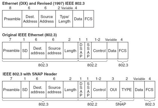 Source: http://internetworkexpert.s3.amazonaws.com/2007/11/ethernet-headers.png
IEEE 802.2 LLC/SNAP frame
By examining the 802.2 LLC header, it is possible to determine whether it is followed by a SNAP (subnetwork access protocol) header. Some protocols, particularly those designed for the OSI networking stack, operate directly on top of 802.2 LLC, which provides both datagram and connection-oriented network services. The LLC header includes two additional eight-bit address fields, called service access points or SAPs in OSI terminology; when both source (SSAP) and destination SAP (DSAP) are set to the value 0xAA, the SNAP service is requested. The SNAP header allows EtherType values to be used with all IEEE 802 protocols, as well as supporting private protocol ID spaces. In IEEE 802.3x-1997, the IEEE Ethernet standard was changed to explicitly allow the use of the 16-bit field after the MAC addresses to be used as a length field or a type field.
*Note: Mac OS uses 802.2/SNAP framing for the AppleTalk V2 protocol suite on Ethernet ("EtherTalk") and Ethernet II framing for TCP/IP.
Thursday, February 19, 2009
Vampire Tap
A vampire tap (also called a piercing tap) is a device for physically connecting a station (i.e. a PC, a printer, or another device) to a network that uses 10BASE5 cabling. This device clamps onto the cable, forcing a spike through a hole drilled through the outer shielding to contact the inner conductor while other spikes bite into the outer conductor. From the vampire tap, a short cable called an AUI (Attachment Unit Interface) is connected directly from the tap to the network card in the PC. Vampire taps allow new connections to be made on a given physical cable while the cable is in use. This allows administrators to expand bus-topology network sections without interrupting communications. Without a vampire tap, the cable has to be cut and connectors have to be attached to both ends.

Source: http://www.blackbox.com/resource/files/applicationdiagrams/athickethvampconnc.GIF
Wednesday, February 18, 2009
Ethernet Physical Layer
The first Ethernet networks, 10BASE5, used thick yellow cable with vampire taps (which we will learn about tomorrow) as a shared medium (using CSMA/CD). Later, 10BASE2 Ethernet used thinner coaxial cable as the shared CSMA/CD (Carrier Sense Multiple Access with Collision Detection) medium. The later StarLAN 1BASE5 and 10-BASE-T used twisted pair connected to Ethernet hubs with 8P8C modular connectors.
Currently Ethernet has many varieties that vary both in speed and physical medium used. Perhaps the most common forms used are 10BASE-T, 100BASE-TX and 1000BASE-T. All three utilize twisted pair cables and 8P8C modular connectors (often called RJ45). They run at 10 Mbit/s, 100 Mbit/s, and 1 Gbit/s, respectively. However each version has become steadily more selective about the cable it runs on and some installers have avoided 1000BASE-T for everything except short connections to servers.
Fiber optic variants of Ethernet are commonly used in structured cabling applications. These variants have also seen substantial penetration in enterprise data center applications, but are rarely seen connected to end user systems for cost/convenience reasons. Their advantages lie in performance, electrical isolation and distance, up to tens of kilometers with some versions. Fiber versions of a new higher speed almost invariably come out before copper. 10 gigabit Ethernet is becoming more popular in both enterprise and carrier networks, with development starting on 40 Gbit/s and 100 Gbps Ethernet. Metcalfe now believes commercial applications using terabit Ethernet may occur by 2015 though he says existing Ethernet standards may have to be overthrown to reach terabit Ethernet.
A data packet on the wire is called a frame. A frame viewed on the actual physical wire would show Preamble and Start Frame Delimiter, in addition to the other data. These are required by all physical hardware. They are not displayed by packet sniffing software because these bits are removed by the Ethernet adapter before being passed on to the host (in contrast, it is often the device driver which removes the CRC32 (FCS) from the packets seen by the user).
Tuesday, February 17, 2009
More advanced networks
Simple switched Ethernet networks, while an improvement over hub based Ethernet, suffer from a number of issues:
· They suffer from single points of failure. If any link fails some devices will be unable to communicate with other devices and if the link that fails is in a central location lots of users can be cut off from the resources they require.
· It is possible to trick switches or hosts into sending data to your machine even if it's not intended for it, as indicated above.
· Large amounts of broadcast traffic, whether malicious, accidental, or simply a side effect of network size can flood slower links and/or systems.
· It is possible for any host to flood the network with broadcast traffic forming a denial of service attack against any hosts that run at the same or lower speed as the attacking device.
· As the network grows, normal broadcast traffic takes up an ever greater amount of bandwidth.
· If switches are not multicast aware, multicast traffic will end up treated like broadcast traffic due to being directed at a MAC with no associated port.
· If switches discover more MAC addresses than they can store (either through network size or through an attack) some addresses must inevitably be dropped and traffic to those addresses will be treated the same way as traffic to unknown addresses, that is essentially the same as broadcast traffic (this issue is known as failopen).
· They suffer from bandwidth choke points where a lot of traffic is forced down a single link.
Some switches offer a variety of tools to combat these issues including:
· Spanning-tree protocol to maintain the active links of the network as a tree while allowing physical loops for redundancy.
· Various port protection features, as it is far more likely an attacker will be on an end system port than on a switch-switch link.
· VLANs to keep different classes of users separate while using the same physical infrastructure.
· Fast routing at higher levels to route between those VLANs.
· Link aggregation to add bandwidth to overloaded links and to provide some measure of redundancy, although the links won't protect against switch failure because they connect the same pair of switches.
Monday, February 16, 2009
Dual Speed Ethernet Hubs
In the early days of Fast Ethernet, Ethernet switches were relatively expensive devices. However, hubs suffered from the problem that if there were any 10BASE-T devices connected then the whole system would have to run at 10 Mbit. Therefore a compromise between a hub and a switch appeared known as a dual speed hub. These devices consisted of an internal two-port switch, dividing the 10BASE-T (10 Mbit) and 100BASE-T (100 Mbit) segments. The device would typically consist of more than two physical ports. When a network device becomes active on any of the physical ports, the device attaches it to either the 10BASE-T segment or the 100BASE-T segment, as appropriate. This prevented the need for an all-or-nothing migration from 10BASE-T to 100BASE-T networks. These devices are also known as dual-speed hubs because the traffic between devices connected at the same speed is not switched.
Subscribe to:
Posts (Atom)

